89
PDP-5020FD
5
6
7
8
5
6
7
8
A
B
C
D
E
F
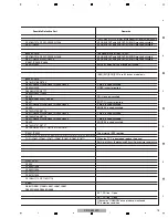
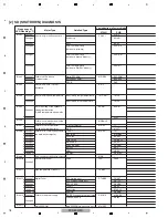
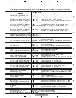
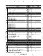
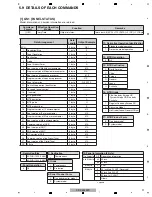
Command
Name
Function
Effective only
in Factory
mode
Active
U-com
Last
Memory
Remarks
%
%
%
%
%
%
%
%
%
%
%
%
%
%
%
%
%
%
%
%
%
%
%
%
%
%
%
%
%
%
%
%
%
%
%
%
%
%
MOD
MAIN
MOD
MOD
MOD
MAIN
MAIN
MAIN
MAIN
MAIN
MAIN
MAIN
MAIN
MAIN
MAIN
MAIN
MOD
MOD
MOD
MOD
MOD
MOD
MOD
MOD
MOD
MOD
MOD
MOD
MOD
MDU MTB
INA
∗∗∗
Switching the terrestrial analog signal, direct tuning
(
∗∗∗
: channel number)
Switching the terrestrial analog signal
INH
Switching the Home Media Gallery
INP
Input switch: INPUT 1
∗∗∗
∗∗∗
INC
Switching the terrestrial digital signal, direct tuning
(
∗∗∗
:channel number)
Switching the terrestrial digital signal
Input switch: INPUT 2
Input switch: INPUT 3
Input switch: INPUT 4
Input switch: INPUT 5
Input switch: INPUT 6
Input switch: INPUT 7
M
MKC
MASK OFF
H ramp (slant 1) M
H ramp (slant 4) M
Slanting ramp M
30 for aging
05 for aging
S06
S00
S01
S02
FBM
OFF (In-phase SUS drive prohibition)
MODE1 (In-phase SUS drive permission)
S00
S01
S21
S03
S04
S05
S06
S07
%
Input switch: INPUT 8 (PC)
S08
S01
S02
S03
%
%
%
%
MIR
Mirror display mode: OFF
Mirror display mode: Right and left inversion
Mirror display mode: Top and bottom inversion
Mirror display mode: Top and bottom and right and left inversion
S00
S01
S02
S03
S04
S05
Erasing afterimage 1
S07
Erasing afterimage 2
S08
White (change in luminance level)
S09
PEAK detection raster
MKS
S10
Address lack check
%
%
MOD
S11
Green vertical line scroll
%
%
MOD
S12
Green horizontal line scroll
%
%
MOD
S13
Vertical ramp vertical scroll (white)
%
%
MOD
S14
Vertical ramp vertical scroll (green)
%
%
MOD
S15
Horizontal ramp horizontal scroll (white)
%
%
MOD
S16
Horizontal ramp horizontal scroll (green)
%
%
MOD
S17
Cross hatch + window
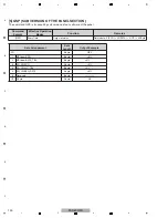
S00
MASK OFF
S01
H ramp (slant 1)
S02
H ramp (slant 4)
I
%
%
%
%
%
%
%
%
%
%
%
%
%
FAJ
Determining the flag of the DIGITAL Assy adjustment in "adjustment is
completed"
FAN
FAY
Factory mode ON
Factory mode OFF
FST
Set each memory setting of MTB/MR side to the shipment state.
F
Note 1: It is necessary to turn off the power for reflecting the setting change.
Note 1
Note 1
Содержание ARP3476
Страница 10: ...10 PDP 5020FD 1 2 3 4 A B C D E F 1 2 3 4 2 2 SPECIFICATIONS ...
Страница 11: ...11 PDP 5020FD 5 6 7 8 5 6 7 8 A B C D E F ...
Страница 12: ...12 PDP 5020FD 1 2 3 4 A B C D E F 1 2 3 4 2 3 PANEL FACILITIES Front Section ...
Страница 13: ...13 PDP 5020FD 5 6 7 8 5 6 7 8 A B C D E F Rear Section ...
Страница 14: ...14 PDP 5020FD 1 2 3 4 A B C D E F 1 2 3 4 Remote Control Unit ...
Страница 15: ...15 PDP 5020FD 5 6 7 8 5 6 7 8 A B C D E F ...
Страница 21: ...21 PDP 5020FD 5 6 7 8 5 6 7 8 A B C D E F ...
Страница 22: ...22 PDP 5020FD 1 2 3 4 A B C D E F 1 2 3 4 4 BLOCK DIAGRAM 4 1 OVERALL WIRING DIAGRAM 1 2 ...
Страница 25: ...25 PDP 5020FD 5 6 7 8 5 6 7 8 A B C D E F OVERALL DIAGRAM PDP 5020FD ...
Страница 31: ...31 PDP 5020FD 5 6 7 8 5 6 7 8 A B C D E F ...
Страница 71: ...71 PDP 5020FD 5 6 7 8 5 6 7 8 A B C D E F ...
Страница 192: ...192 PDP 5020FD 1 2 3 4 A B C D E F 1 2 3 4 9 6 PANEL CHASSIS SECTION ...

