background image

Chapter 4: Troubleshooting

42

 Deko1000 & Deko550 Technical Reference And Service Guide

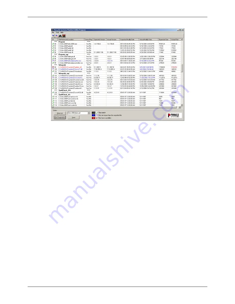
Figure 4-22: Example Deko Manifest results with possible problems

Important:


It does not necessarily mean that the Deko1000 or Deko550 workstation being tested is 

malfunctioning just because the results of a Deko Manifest test my have blue or red files indicated.  In fact, 
some workstations are suppose to have files indicated this way.  This is why it is absolutely imperative that 
a Pinnacle Systems Customer Support representative interprets the test results and recommends to you how 
to proceed.  This is also why the Internet Explorer .html file of the Deko Manifest results saved in the 
procedures above must be sent to Customer Support.  Contact information can be found in “Appendix A: 
Pinnacle Systems Technical Support.”

Содержание Deko1000

Страница 1: ...DEKO1000 DEKO550 TechnicalReferenceAndServiceGuide Pinnacle Systems Inc 280 N Bernardo Avenue Mountain View CA 94043 July 2004 Copyright 2004 Pinnacle Systems Inc P N 372100105 Rev A ...

Страница 2: ...72101002 Deko1000 Dual Channel System Model 325100550 Deko550 Single Channel System Model 325100552 Deko550 Dual Channel System If the model number of your Deko1000 or Deko550 system does not appear in the list above please refer to the Quick Install document that was provided on the Application CD with the original shipment of your system Trademarks All brand or product names mentioned herein are...

Страница 3: ...ghts You may not copy the Software except that it may make a single copy for archival purposes You may not modify the Software or permit or assist any third party in doing so You may not decompile reverse engineer disassemble or otherwise reduce the Software to source code or other human readable form or attempt or permit any third party to do so Any violation of this Software license shall be a m...

Страница 4: ...E SYSTEM FOR COMMERCIAL LOSS OF ANY KIND FOR THE PROCUREMENT OF SUBSTITUTE GOODS WHETHER ARISING IN TORT CONTRACT OR ANY OTHER LEGAL THEORY EVEN IF PINNACLE HAS BEEN ADVISED OF THE POSSIBILITY OF SUCH DAMAGES IN ANY EVENT PINNACLE S LIABILITY SHALL BE LIMITED TO THE AMOUNT ACTUALLY PAID BY YOU FOR THE SYSTEM GIVING RISE TO ANY SUCH DAMAGE THIS LIMITATION IS INTENDED TO LIMIT PINNACLE S LIABILITY A...

Страница 5: ...D SETUP 17 Contents 17 Unpacking 18 Deko1000 and Deko550 Workstation Initial Setup 19 Repacking A Deko1000 Or Deko550 Workstation 21 Deko1000 and Deko550 Hardware Settings Window 22 Deko1000 and Deko550 GPI Input And Output Connections 24 GPI Input 24 GPI Output 24 Network Configuration 25 CHAPTER 4 TROUBLESHOOTING 27 Contents 27 Inflexion I O Diagnostic Utility 28 Modes Of Operation 28 Setup Befo...

Страница 6: ...ard Drive 80 Configuring A New Media Hard Drive 86 APPENDIX A PINNACLE SYSTEMS CUSTOMER SUPPORT 93 About Deko Support 93 Troubleshooting Questionnaire 93 Contacting Pinnacle Systems 93 Upgrade Information on the Internet 94 APPENDIX B USING SHAPED AND UNSHAPED KEYING 95 About Shaped And Unshaped Keying 95 Shaped vs Unshaped Compositing 95 Shaped 95 Unshaped 96 Mathematical Equations 96 Comparison ...

Страница 7: ...is Chapter provides an introduction to the Deko1000 and Deko550 Workstation Technical Reference and Service Guide A brief description of all of the Chapters and Appendices that can be found in this document is also described in this section This Chapter contains the following sections Introduction Using This Manual ...

Страница 8: ... Deko550 System Overview Important This manual references only newer Deko1000 and Deko550 systems that were shipped after July 2004 and includes the model numbers listed below Model 372101000 Deko1000 Single Channel System Model 372101002 Deko1000 Dual Channel System Model 325100550 Deko550 Single Channel System Model 325100552 Deko550 Dual Channel System If the model number of your Deko1000 or De...

Страница 9: ...o resources a troubleshooting questionnaire and regional worldwide e mail and internet contact information is included here Appendix B Using Shaped and Unshaped Keying An explanation about the methodology and differences between shaped and unshaped keying when combining video and key elements is given here Appendix C Deko1000 and Deko550 Technical Specifications Gives the technical specifications ...

Страница 10: ...Chapter 1 Introduction To Deko1000 and Deko550 10 Deko1000 Deko550 Technical Reference And Service Guide ...

Страница 11: ...d various channel configurations for a typical Deko1000 or Deko550 workstation are discussed and also detailed via illustrations The inputs and outputs on the front and back panel of the Deko1000 and Deko550 workstation are also described This Chapter contains the following sections Hardware Configuration Channel Configurations Deko1000 and Deko550 Workstation Front Panel Deko1000 and Deko550 Work...

Страница 12: ...n a Single Channel or Program Preview configuration Each Deko1000 and Deko550 workstation will be in one of these configurations depending on how the workstation was ordered Each one of these configuration types is described below Single Channel Mode In single channel mode a single TARGA 3200 board is installed in a Deko1000 or Deko550 workstation All I O clip processing effects output and keying ...

Страница 13: ...isplayed on the Preview window within the Deko1000 or Deko550 software program Important No effects or clips can be output from the second TARGA 3200 board as Program Preview An illustration that is representative of the signal flow for Program Preview mode processing is shown in Figure 2 2 Figure 2 2 Program Preview mode processing Note The Clip or DekoObjex options may or may not be installed on...

Страница 14: ...right front panel has openings for inserting floppy disks and DVDs or CDs To power on either machine first turn on the Power Supply switches on the back of a unit then press the Power On Off button on the left side of the front panel To power off either machine first close all applications and shut down the Windows operating system Then turn off the Power Supply switches on the back of the machine...

Страница 15: ...of a Power Supply failure Contact Pinnacle Systems Customer Support refer to Appendix A for ordering information Turn on the Power Supply switches before pressing the Power On Off switch on the front panel When the power supplies are running the Power LED on each power supply is green When a power supply is turned off or is not operational the LED for that power supply is not lit If a power supply...

Страница 16: ...Chapter 2 Deko1000 and Deko550 System Overview 16 Deko1000 Deko550 Technical Reference And Service Guide ...

Страница 17: ...ormation on installing the hard drives attaching peripheral devices testing the workstation Deko1000 and Deko550 hardware settings software setup and GPI control and network connections This Chapter contains the following sections Unpacking Deko1000 and Deko550 Workstation Initial Setup Deko1000 and Deko550 Hardware Settings Window Deko1000 and Deko550 GPI Input and GPI Output Connections Network ...

Страница 18: ...lease Notes Deko1000 or Deko550 Quick Install Guide Product Registration Card Please read the Release Notes for important information about your new Deko1000 or Deko550 System Also take the time to fill out the Product Registration Card and return it to Pinnacle Systems Your filling out and sending the registration card enables Pinnacle Systems to inform you of any important updates for your Deko1...

Страница 19: ...nel of the Deko1000 or Deko550 workstation Refer to Figure 3 1 When placing a hard drive into its respective bay align the drive so that it will properly slide into the drive bay Then push the drive so that it completely slides into the bay This will connect the drive to its connectors at the back of the bay Use a screwdriver to completely tighten the two thumbscrews To insure that the connection ...

Страница 20: ... where the AC Power Cords are connected to On Then push the On Off button located on the front panel of the workstation to power up the workstation When the operating system boots up the Deko1000 or Deko550 background is displayed on the monitor 8 Run the automatic mode of the Inflexion I O Diagnostic Utility to insure that the TARGA card s are functioning on the workstation For each TARGA card to...

Страница 21: ...gram can be found in Chapter 4 Troubleshooting of this manual 9 If the workstation is to be rack mounted or moved to another location disconnect all of the components and rack mount the workstation chassis Each Deko1000 and Deko550 workstation chassis is designed so that industry standard rails can be connected for rack mounting purposes Each workstation will fit on 19 inch standard instrument rac...

Страница 22: ...gured to run in either NTSC or PAL video standards Select the format from the Video Standard drop down menu Video Characteristics_Aspect Ratio Deko1000 and Deko550 can be configured to run in either 4x3 or 16 9 aspect ratios This will control how the Deko application is laid out and how graphics are created Select the format from the Aspect Ratio drop down menu Video Characteristics_Output H Timin...

Страница 23: ...meter provides configuration control for the Video input on each channel The Embedded Audio parameter controls whether or not embedded audio is to be used on the Video input channel If Yes is selected the audio channels selected in the Audio Characteristics menu will be used Input B SDI Key A in _Use This Input This parameter provides configuration control for the Key input on each channel The Key...

Страница 24: ...d contact closure such as a GPI output from a switcher Alternatively a short pulse minimum 10 milliseconds on pin 1 will also trigger the GPI input on the Deko application GPI Output Pin 7 on the RS 232 connector will pulse high for approximately 100 milliseconds when a GPI output command is issued from the Deko application This can be used to trigger an external device that is expecting a pulse t...

Страница 25: ...oduce a serious security risk 3 Do not store files with a exe extension in directories with write permissions 4 If possible keep all Pinnacle Live Production equipment on a separate network that is iso lated from other machines in the facility 5 Disallow Internet access on any Pinnacle Live Production machines that do not require it 6 Do not install anti virus software on any of the Pinnacle suppl...

Страница 26: ...Chapter 3 Installation And Setup 26 Deko1000 Deko550 Technical Reference And Service Guide ...

Страница 27: ...00 and Deko550 Workstation system software as a means to quickly and easily troubleshoot the workstation Troubleshooting tips are also provided Performing these procedures will help streamline the process of getting your Deko1000 or Deko550 Workstation up and running again This Chapter contains the following sections Inflexion I O Diagnostic Utility Deko Manifest Utility ...

Страница 28: ... Of Operation The Inflexion I O Diagnostic test can be used in two different modes automatic or manual The automatic testing runs a list of tests until either an error is detected or until all the tests are successfully completed In most instances the automatic test mode is used Manual testing allows you to select a test individually from the list of tests and run it You can run each test individu...

Страница 29: ... or Deko550 Workstation by way of the Inflexion I O Diagnostic Utility test 1 Turn on the Deko1000 or Deko550 Workstation Only the Windows OS should be running If any other programs are running on the workstation then you should exit out of those programs Important If your workstation is corrupted to the point where it will not boot up when turned on contact Pinnacle Systems Technical Support Cont...

Страница 30: ...d This TARGA card is essentially the second channel If you are facing the back panel of the workstation and looking into the TARGA card bay area then Board 2 would be the second TARGA card from the left Refer to Figure 5 1 within the Replacing Workstation Com ponents section of Chapter 5 for TARGA card locations Board 3 This pull down selection is not used because workstations configured for two c...

Страница 31: ...og stating that the tests are done and all test passed will be displayed Click the OK button within the dialog Refer to Figure 4 5 Figure 4 5 Dialog shown when all automatic tests pass If there is more than one TARGA card in your workstation repeat Steps 1 4 above for each TARGA card If an automatic test fails The automatic testing sequence will stop at the point that a test fails and the dialog s...

Страница 32: ...d properly connected before repeating the automatic test sequence Important Power down the workstation before removing the cover to make sure that the TARGA card is properly seated in its PCI slot 2 If the test fails again click OK on the Failed Test dialog and save results Results can be saved by right clicking on the blue title bar or red icon upper left hand corner of the Inflexion I O Diagnost...

Страница 33: ...l Support may request that you send this file to them An example of a saved Test Results file is shown in Figure 4 9 Figure 4 9 Example of a saved Test Results file 5 Contact Pinnacle Systems Technical Support Pinnacle Systems Technical Support will provide you instructions on the procedure to obtain a replacement TARGA card Contact information can be found in Appendix A Pinnacle Systems Technical...

Страница 34: ...gnostic program is running 3 Select the channel that is to be tested Some workstations have more than one channel There is a pull down selection box on the upper left hand side of the Inflexion I O Diagnostic window The default selection in the pull down is Board 1 i e first channel Refer to Figure 4 10 If more than one channel is in the workstation click and hold the pull down and then select the...

Страница 35: ...that the various components on the TARGA card are functioning in a normal manner Note Depending on the model of the TARGA card in your system the 3210 indication may appear as a different number Memory Tests This test performs extensive memory testing on the TARGA card Hub Clock Rate This is a test to check that the TARGA s clock locks to the oscillator SDI Channel Tests This test loops a signal o...

Страница 36: ...the SDI Channel tests that failed check that the loop through cables are connected properly to the TARGA card being tested If a genlock tests failed check the signal input on the Reference Refer to the Setup Before Testing section above for manual testing setup procedures Perform the following steps if a test fails 1 Repeat the manual test Make sure that the TARGA card is properly seated and loop ...

Страница 37: ...e Enter key on your keyboard The Enter key will cause the Save Results window to unexpectedly close 4 Click the Save button The Save Results file will be saved in the same folder where the Inflexion I O Diagnostic test is located on the Deko1000 or Deko550 Workstation Pinnacle Systems Technical Support may request that you send this file to them An example of a saved Test Results file is shown in ...

Страница 38: ...lyze the results of this test and then determine the steps necessary to solve the problem being experienced with the workstation Deko Manifest Test Procedure The following steps should be followed to performed the Deko Manifest Utility test 1 Turn on the Deko1000 or Deko550 Workstation Only the Windows OS should be running If any other programs are running on the workstation then you should exit o...

Страница 39: ...00 or Deko550 software Inflexion_Manifest This choice will compare the Inflexion software programs on the worksta tion being tested to the official record of the Pinnacle Systems release for the Inflexion software Figure 4 17 Software components selection for Manifest Utility test 4 Click the Run Diagnostics button on the Manifest Utility program window Clicking the Run Diagnostics program will ca...

Страница 40: ...st Utility program window to capture the window and save the results When the Save button is clicked a Save File As window similar to that shown in Figure 4 19 will be displayed Figure 4 19 Example File Save As Window From the Save in pull down at the top upper left of the File Save As window select the location that the result of the Deko Manifest test will be saved Refer to Figure 4 20 Figure 4 ...

Страница 41: ... Refer to Figure 4 17 Your choice will either be Deko1000 or Deko550 and Inflexion_Manifest 8 Perform Steps 4 and 5 listed above to complete testing Once the second set of file components file has been tested and saved Deko Manifest Utility testing is completed Follow the instructions given to you by Pinnacle Systems Customer Support in order to get the saved files to them Interpreting Deko Manife...

Страница 42: ...fest test my have blue or red files indicated In fact some workstations are suppose to have files indicated this way This is why it is absolutely imperative that a Pinnacle Systems Customer Support representative interprets the test results and recommends to you how to proceed This is also why the Internet Explorer html file of the Deko Manifest results saved in the procedures above must be sent t...

Страница 43: ...or cases when the entire Deko1000 or Deko550 operating system must be replace on or restored onto a Deko1000 or Deko550 workstation Please note that Deko1000 and Deko550 Workstation components should only be replaced if you are directed to so by a Pinnacle Customer Support representative This Chapter contains the following sections Replacing Workstation Components System Recovery Procedures Config...

Страница 44: ...wer Supply Fan DVD CD Drive And Floppy Drive The physical location of each component listed above for a Deko1000 or Deko550 Workstation is shown in Figure 5 1 Figure 5 1 Replaceable components within a Deko1000 or Deko550 Workstation Any components not listed above that needs to be replaced within a Deko1000 or Deko550 Workstation should only be replaced by a qualified Pinnacle Systems service eng...

Страница 45: ...enu Shut Down Turn off the monitor after you are sure the computer has powered down Important Do not attempt to open the computer while the computer is turned on If you think the computer is in sleep mode press the power button in front of the computer to wake it and then shut down the computer 2 Remove all cables from the back of the computer and let the computer cool down Unplugging the power co...

Страница 46: ...er to Figure 5 3 Figure 5 3 BNC I O Connection Plate with internal BNC cables to TARGA Card 6 Remove all of the internal BNC cables from the BNC connectors on the TARGA card Each BNC cable grip must be turned counter clockwise to loosen Once loosened a BNC can be pulled from the TARGA s BNC connector Remove all of the BNC cables from the TARGA card including the REF BNC cable if it is used and set...

Страница 47: ...to the TARGA card remove the handle so that the TARGA looks similar to that shown in Figure 5 2 11 Insert the new TARGA card into the expansion slot Note The same expansion slot that the damaged card was pulled from should be used With the bracket toward the open access port align the connector on the bottom of the card directly over the slot Then push down and gently rock the card lengthwise unti...

Страница 48: ...h the BNC I O Connection Plate and connect the external BNC cables to it Push the I O Connection Plate back into place on the computer s frame and tighten the two spring screws on the plate to fasten it into place Then connect all of the external BNC cables to the front of the BNC I O Connection Plate 16 Attach the Fan Cover and Workstation Support Brace Place the Fan Cover on top of the fan housi...

Страница 49: ... Test application should be used to check the functionality of the newly installed TARGA card For systems with more than one TARGA card the first TARGA card TARGA Board 1 is seated in PCI Slot 3 which is the third PCI slot from the SVGA card If there is a second TARGA card then it will be in Slot 4 Refer to Figure 5 1 for TARGA card locations Refer to Chapter 4 Troubleshooting for instructions on ...

Страница 50: ...own the computer and turn off the monitor Shut down the computer by going to the Start menu and selecting Shut Down Start menu Shut Down Turn off the monitor after you are sure the computer has powered down Important Do not attempt to open the computer while the computer is turned on If you think the computer is in sleep mode press the power button in front of the computer to wake it and then shut...

Страница 51: ...wise rocking motion Note If there is a tie wrap binding the wiring you may have to remove i e cut the tie wrap 7 Remove the new SVGA card from its antistatic bag Make sure you are grounded via the antistatic wrist strap Handle the card by its edges and by its metal bracket and avoid touching the connector pins on the bottom of the card 8 Insert the new SVGA card into the AGP slot With the bracket ...

Страница 52: ...omer Support representative The Hard Drives are accessed from the front panel of a Deko1000 or Deko550 Workstation if it becomes necessary to install a replacement Refer to Figure 5 9 Figure 5 9 Workstation Front Panel with panel cover removed Refer to Figure 5 10 for Hard Drive identification Figure 5 10 Deko1000 and Deko550 Workstation Hard Drive 1 Shut down the computer and turn off the monitor...

Страница 53: ...captive thumbscrews of the damaged drive Use a screwdriver if necessary to completely loosen the two thumbscrews The screws are captive meaning that they can be loosened but not removed from the front bay panel 4 Pull the Hard Drive out from its drive bay Grab the two thumbscrews and pull to slide the Hard Drive out from the drive bay Refer to Figure 5 11 Figure 5 11 Hard drive out from drive bay ...

Страница 54: ...d on the VGA monitor Important If an Operating system not found message is displayed on the monitor the captive thumbscrews for the new drive may not be tighten enough Use a screwdriver to tighten the screws as much as possible and then power down and power up the workstation Important If video is not displayed on the VGA monitor check all of the connections If is still not displayed contact Pinna...

Страница 55: ... Power Supply unit starts to malfunction the LED on the unit will dim and eventually turn off A Workstation Power Supply unit is shown in Figure 5 13 Figure 5 13 Power Supply The Power Supplies are accessed from the back of a Deko1000 or Deko550 Workstation if it becomes necessary to install a replacement A Power Supply can be replaced hot That is a Power Supply can be replaced while the Deko1000 ...

Страница 56: ...wer Supply so that it completely slides into the bay This will connect the Power Supply to its connectors at the back of the bay Make sure the locking latch slides down to lock the Power Supply into place 5 Plug in power cord and switch Power Supply to On When the Power Supply is switched to the On i e I position its LED should light Important If the LED on the unit does not light check both ends ...

Страница 57: ...r button in front of the computer to wake it and then shut down the computer 2 Remove all cables from the back of the computer and let the computer cool down Unplugging the power cord and cables helps to ensure that no power is running on the motherboard which reduces the risk of damage to your equipment Wait 5 minutes to allow the computer s internal components to cool 3 Discharge static electric...

Страница 58: ...he Fan within the Fan Box There are access holes in the Fan Box that provide access to the fan retaining screws Refer to Figure 5 18 Use a screw driver to loosen or remove each screw so that the Fan can be lifted out the top of the Fan Box Note A magnetic screwdriver may be needed to more easily remove the fan screws Figure 5 18 Access Holes To Fan Retaining Screws 8 Lift the Fan out of the workst...

Страница 59: ...station Support Brace Place the Fan Cover on top of the fan housing and screw the cover back into place with the three cover screws previously removed Put the Workstation Support Brace back in place just above the TARGA card s and other cards Refer to Figure 5 1 Screw the brace into place at both ends with its previously removed screws 14 Attach all other cables to the computer Connect power cord ...

Страница 60: ...omputer has powered down Important Do not attempt to open the computer while the computer is turned on If you think the computer is in sleep mode press the power button in front of the computer to wake it and then shut down the computer 2 Remove all cables from the back of the computer and let the computer cool down Unplugging the power cord and cables helps to ensure that no power is running on t...

Страница 61: ...onnector and then the power connector from the back of the DVD CD Drive Refer to Figure 5 21 Figure 5 21 Motherboard ribbon and power cables connected to DVD CD and Floppy Drive 7 Disconnect the power connector and ribbon cable from back of the Floppy Drive Pull the other i e shorter motherboard ribbon connector and then the power connector from the back of the Floppy Drive Refer to Figure 5 21 8 ...

Страница 62: ...re 2 screws on the top side of the housing and 2 screws on the bottom side of the housing that keeps the DVD CD Drive in place Refer to Figure 5 23 Remove the screws Figure 5 23 Bottom of DVD CD Floppy housing assembly 11 If the Floppy Drive is to be replaced remove the screws securing the Floppy Drive in the DVD CD Floppy housing assembly There are 4 screws on the top of the housing and 4 screws ...

Страница 63: ...Drive Connect the shorter motherboard ribbon connector and then the power connector to the back of the Floppy Drive Refer to Figure 5 21 15 Connect the power connector and ribbon cable to the back of the DVD CD Drive Connect the longer motherboard ribbon connector and then the power connector to the back of the DVD CD Drive Refer to Figure 5 21 16 Connect the 2 thick wired USB connectors to the mo...

Страница 64: ...been connected upside down If such is the case shut down the workstation and reattach the offending ribbon cable If video is not displayed on the VGA monitor then check all of the connections If video is still not displayed then contact Pinnacle Customer Support Refer to Appendix A for contact information 19 Place the computer s cover back on the computer Use a Phillips head screwdriver to reattac...

Страница 65: ...acle Systems below You will be able to completely restore your workstation in about 20 minutes If you don t have the Deko1000 or Deko550 Drive Image Restore DVD but you do have the Deko1000 or Deko550 Software CD then proceed to the section called Recreating A Deko1000 or Deko550 Drive Image Restore DVD below Pinnacle Systems has provided a way for you to create the Drive Image Restore DVD that is...

Страница 66: ... sure Important This process will permanently delete all of the material on your C Drive Be sure to back up all important material on your C Drive before proceeding with this process Select Yes The Drive Image Restore program will take approximately 6 minutes to complete After the program has finished the root directory for Drive A shown as A will be displayed 5 Remove the Drive Image Restore DVD ...

Страница 67: ...ext is clicked the software will load and the system will reboot 12 Click Next on the initial screen of the Network Identification Wizard program The Network Identification Wizard program automatically launches after the system reboots After next is clicked a Users Of This Computer screen will appear 13 Click Next on the Users Of This Computer screen Use the default settings Do not type in a passw...

Страница 68: ...ard Drives letter designations The designations for the drives should be changed as follows Drive Disk 0 System partition should have a designation of C Drive Disk 0 Graphics partition should have a designation of D Drive Disk 1 Clips partition should have a designation of E Drive DVD CD ROM 0 should have a designation of F Check the hard drive letter designations by right clicking on My Computer ...

Страница 69: ...ement selected If the drive letter designations are as follows go to Step 5 Drive Disk 0 System equals C Drive Disk 0 Graphics equals D Drive Disk 1 Clips equals E Drive DVD CD ROM 0 equals F If the designation letters do not match what is listed above an example of the procedure for changing drive letters is as follows Right click on the drive word Clips D and select Change Drive Letters and Path...

Страница 70: ...w drive designation to be assigned to Clips and then click Ok Refer to Figure 5 31 Figure 5 31 H designation selected for Clips Drive Select Yes to confirm that the drive designation is to be assigned Refer to Figure 5 32 Figure 5 32 Confirmation of drive designation Right click on the partition word Graphics E and select Change Drive Letters and Paths from the pop up window Refer to Figure 5 33 F...

Страница 71: ...new drive designation to be assigned to Graphics and then click Ok Refer to Figure 5 35 Figure 5 35 D designation selected for Graphics Select Yes to confirm that the drive designation is to be assigned Refer to Figure 5 36 Figure 5 36 Confirmation of drive designation Right click on the partition word Clips H and select Change Drive Letters and Paths from the pop up window Refer to Figure 5 37 Fi...

Страница 72: ...assigned to Clips and then click Ok Refer to Figure 5 39 Figure 5 39 E designation selected for Clips Drive Select Yes to confirm that the drive designation is to be assigned Refer to Figure 5 40 Figure 5 40 Confirmation of drive designation Repeat the process for any remaining partitions that need to be changed Make sure the partition designations are the same as those shown in Figure 5 41 below ...

Страница 73: ...are as follows 1 Insert the Deko1000 or Deko550 Software CD into DVD CD ROM drive The software program should auto start If it does not auto start browse the CD and click on the Setup exe file Click Next for the screen that appears 2 Accept the license agreement Click to check the Yes I accept radio button and then click Next The product key confirmation screen will appear 3 Choose the Custom Inst...

Страница 74: ...drive on the Deko1000 or Deko550 workstation will not properly burn a DVD that has a format of R or RW Perform the following steps to recreate a Deko 300 Drive Image Restore DVD 1 Power up the workstation and insert a blank DVD into the DVD CD ROM drive If necessary close the Drive F window if it is displayed since nothing is on the DVD at this time 2 Start the software program named Instant CD DV...

Страница 75: ...l button Refer to Figure 5 43 5 Click the New Project menu icon A New Disc Project window similar to that shown in Figure 5 44 will be displayed Figure 5 44 New Disc Project window 6 Click the Advanced Projects box Click to check mark the Advanced Projects box Refer to Figure 5 44 7 Select Raw ISO Data Click to highlight Raw ISO data and then click Next Refer to Figure 5 45 ...

Страница 76: ...ected 8 Browse to the Track1 iso file on Drive E Clips drive within the System Restore folder Once you have browsed to the Track1 iso file click Next Refer to Figure 5 46 Figure 5 46 Browsing to Track1 iso file 9 Select Close This Wizard and click Finished Refer to Figure 5 47 Figure 5 47 Close This Wizard selected ...

Страница 77: ...ng Raw file within Disc Projects subdirectory Once the Properties menu icon is clicked a window showing of the Properties Of Raw will be displayed Refer to Figure 5 49 Figure 5 49 Properties Of Raw window displayed 11 From the pull down for Disk Type select DVD Select DVD as the Disc Type that is in the DVD CD ROM drive and then click Ok Refer to Figure 5 49 12 Click Write in the icon menu Refer t...

Страница 78: ... image of the Deko1000 or Deko550 operating system is now ready to be copied to the DVD Figure 5 51 Write Disc Project window displayed 13 Click the Write button in the Write Disk Project dialog Click the Write button to begin writing the Deko1000 or Deko550 operating system to the DVD Refer to Figure 5 51 Once the Write button is click a window indicating the progress of the data being written on...

Страница 79: ...5 53 Successful creation of Deko1000 or Deko550 Drive Image Restore DVD 15 Quit the Instant CD DVD software program The Deko1000 or Deko550 Drive Image Restore DVD you just created can now be used to restore the Deko1000 or Deko550 operating system Refer to the section You Have The Software DVDs Supplied By Pinnacle Systems above for instructions on restoring the Deko1000 or Deko550 operating syst...

Страница 80: ... up Enter the BIOS program by rebooting the workstation and then at the beginning of the start up procedure press and momentarily hold down the F2 key on the keyboard This is done when you see the words Press F2 for Setup on the monitor or when you see the three keyboard Lock LEDs top right hand corner of the keyboard flash on the keyboard 3 Insert the Drive Image Restore DVD into the DVD CD ROM d...

Страница 81: ... name of the computer should appear 9 Enter a name for the computer and click Next Only the characters A Z the numbers 0 9 and hyphens can be used If the workstation is connected to a network then name given to the machine and the description if one is given will appear on the network When Ok is clicked the Administrator password screen will appear 10 Select the Network Settings for the workstatio...

Страница 82: ... color This is done by navigating the following path Right click on desktop Properties Settings tab Clicking the Settings tab will then show a window similar to that shown in Figure 5 54 Figure 5 54 Display Properties window Use the slider to adjust the screen resolution and bit depth to 1024x768 with 32 bit color Then click Ok and then Yes to keep the new resolution and color depth 18 Right click...

Страница 83: ...for Disk 0 and select Create Partition Refer to Figure 5 56 Figure 5 56 Select Create Partition for Drive 1 20 The Create Partition Wizard will appear Click Next Refer to Figure 5 57 Figure 5 57 Partition Wizard Window 21 Select Primary as the partition type and click Next Refer to Figure 5 58 Figure 5 58 Select Primary as the type ...

Страница 84: ...ve letter Click Next Refer to Figure 5 60 Figure 5 60 Drive letter designation 24 The Volume label name must be Graphics and the box for Perform a Quick For mat must be check marked Make sure you spell the word Graphics correctly If any other name is used here the drive will not work Refer to Figure 5 61 Click the Perform a Quick Format box to place a check mark there Click Next to continue Figure...

Страница 85: ...ssful completion Of Create Partition Wizard The drive will format When formatting is complete the drive partitioning for the workstation should look as shown in Figure 5 63 Figure 5 63 Successful formatting of drive 26 Place any material you previously backed up from your old System Graphics D hard drive to the new System Graphics D hard drive ...

Страница 86: ... Enter the BIOS program by rebooting the workstation and then at the beginning of the start up procedure press and momentarily hold down the F2 key on the keyboard This is done when you see the words Press F2 for Setup on the monitor or when you see the three keyboard Lock LEDs top right hand corner of the keyboard flash on the keyboard 3 Insert the Drive Image Restore DVD into the DVD CD ROM driv...

Страница 87: ... name of the computer should appear 9 Enter a name for the computer and click Next Only the characters A Z the numbers 0 9 and hyphens can be used If the workstation is connected to a network then name given to the machine and the description if one is given will appear on the network When Ok is clicked the Administrator password screen will appear 10 Select the Network Settings for the workstatio...

Страница 88: ...esolution of 1024x768 with 32 bit color This is done by navigating the following path Right click on desktop Properties Settings tab Clicking the Settings tab will then show a window similar to that shown in Figure 5 64 Figure 5 64 Display Properties window Use the slider to adjust the screen resolution and bit depth to 1024x768 with 32 bit color Then click Ok and then Yes to keep the new resoluti...

Страница 89: ... 5 66 Figure 5 66 Select Write Signature for Drive 1 20 Check that Disk 1 is check marked for a signature to be written Click the Disk 1 box to place a check mark there Click Next to continue Figure 5 67 Partition format designations 21 Right click on the unallocated black area for Disk 1 and select Create Partition Refer to Figure 5 68 Figure 5 68 Select Create Partition for Drive 1 ...

Страница 90: ... will appear Click Next Refer to Figure 5 69 Figure 5 69 Partition Wizard Window 23 Select Primary as the partition type and click Next Refer to Figure 5 70 Figure 5 70 Select Primary as the type 24 Use the maximum disk space for the partition size Click Next Refer to Figure 5 71 Figure 5 71 Maximum disk size selected ...

Страница 91: ...be Clips and the box for Perform a Quick Format must be check marked Make sure you spell the word Clips correctly If any other name is used here the drive will not work Refer to Figure 5 73 Click the Perform a Quick Format box to place a check mark there Click Next to continue Figure 5 73 Partition format designations 27 Click Finished Refer to Figure 5 74 Figure 5 74 Successful completion Of Crea...

Страница 92: ...e drive will format When formatting is complete the drive partitioning for the workstation should look as shown in Figure 5 75 Figure 5 75 Successful formatting of drive 28 Place any material you previously backed up from your old Media Clips E hard drive to the new Media Clips E hard drive ...

Страница 93: ... or added to the system 5 What is the exact wording of any error messages you have received 6 Are you using the product as it was intended or recommended to be used 7 Does the issue disappear if you boot the system with all third party devices removed 8 What have you done to try to resolve the issue yourself Once you know the answers to the questions listed above you should contact Pinnacle System...

Страница 94: ...egions Taiwan India Pakistan Bangladesh Sri Lanka Australia New Zealand Thailand Viet Nam Philippines Brunei Singapore Malaysia Indonesia Broadcast Support Beijing E mail broadcast support cn pinnaclesys com Web Support http www pinnaclesys com support contact Supports Regions China Hong Kong Korea Broadcast Support Japan E mail broadcast pinnaclesys co jp Web Support www pinnaclesys co jp Upgrade...

Страница 95: ...sion and improper operation Shaped vs Unshaped Compositing In the broadcast environment video and key signals are normally transported on two separate signals The terms Shaped and Unshaped refer to how a separate key signal is used in conjunction with an associated video or fill signal to represent a non opaque source Shaped Shaped refers to a video and key pair that has the key pre applied or pre...

Страница 96: ...unshaped Two distinct mathematical functions are used depending on the format of the keyed inputs For the mathematically inclined the equations are provided below Unshaped Keying uses the following equations for mixing two Video Key sources Kout Kforeground Kbackground 1 Kforeground Vout Vforeground KX Vbackground 1 KX where KX Kforeground Kforeground Kbackground Kout Shaped Keying uses the follow...

Страница 97: ... comparison matrix below summarizes some of the main differences between working in the shaped and unshaped domain Shaped Unshaped Keying Process Additive Simple Multiplicative More Complex Preview Previewing video properly displays transparency properties Previewing video does not display transparency properties No soft borders Standardization Most Graphics Compositing and computer based systems ...

Страница 98: ...Appendix B Using Shaped And Unshaped Keying 98 Deko1000 Deko550 Technical Reference And Service Guide ...

Страница 99: ...ronous Inputs SDI and Key Output per Channel SMPTE 259M Compliant Horizontal Output Timing Adjustment 300 µsec to 300 µsec half pixel increments Standard 8 Bit 4 2 2 4 Sampling Preserves VBI Data in Lines 10 21 Audio I O Four Channels Audio Input Embedded in SDI Video Inputs Eight Channels Audio Output Embedded in SDI Video Inputs Standard 16 Bit 48 KHz Sampling Reference Analog Color Black 75 ohm...

Страница 100: ...10 220 Volt 60 50 Hz Auto sensing AC Line Current 6 A 350 Watt Maximum Output ClipDeko Option Audio I O Four Channels of Audio for Clip Capture Embedded in SDI Video Inputs Eight Channels of Audio for Clip Playback Embedded in SDI Video Outputs Standard 16 Bit 48 KHz Sampling Clip Capture Support MPEG2 I Frame 4 2 2 Sampling Variable Bit Rate 15 50 MBit MXF File Format DV25 Standard Compression Fo...

Страница 101: ...x Option Note The DekoObjex option is not available on the Deko550 system DekoObjex Processing 32 Bit 4 4 4 4 RGBA Processing Up to 5 Screen Pixel Coverage Processing Power Live Video Processing Independent 2D DVE for Two Video Inputs 4 Frame Processing Delay through Box Audio Processing 24 Track Audio Mixer with Router ...

Страница 102: ...Appendix C Deko550 and 1000 Technical Specifications 102 Deko1000 Deko550 Technical Reference And Service Guide ...

Отзывы: