32
3 . I N S T A L L A T I O N
M u l t i p l e S w i t c h C o n f i g u r a t i o n s
WARNING
: Ensure that the switch is independently grounded with a wire from Ground securely
attached to the ground lug at the rear of the switch. See ESD Procedure, page 18.
Note
: The PoLRE switch will power up immediately and begin system status verification.
Multiple Switch Configurations
Multiple PoLRE switches can be installed together in the same equipment rack for power and load sharing
between multiple PoLRE switches. A fully redundant ring can be created, providing redundant power to
any switch that has a power failure.
Daisy-chaining PoLRE Switches for Powershare
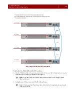
Up to 4 PoLRE switches can be daisy-chained together for Powershare. They are connected in a ring using
the DC In/Out connectors at the rear of the switch. If a power fault occurs on any switch in the ring, the
others are able to share the load, and the affected switch continues to function normally.
CAUTION
:
Powershare Mode is not intended to be a permanent operating mode. If the power
supply unit of a PoLRE switch should fail, you must replace it as soon as possible.
The illustration on the next page shows how multiple PoLRE switches can be interconnected using the two
DC In/Out connectors at the rear of each switch. Apply this illustration to your particular environment
before continuing with the procedure that follows the illustration.
Note
: This procedure requires that you have the following on hand:
•
The additional PoLRE switches and their accessories, including the DC cables.
•
At least one switch must be powered with an AC connection. Typically, all switches are AC powered
before you begin.
Содержание PoLRE
Страница 1: ...PoLRE Switch Hardware Installation Guide Release 1 2...
Страница 22: ...16 2 U NP AC KI NG Before Y ou I ns tall...
Страница 46: ...40 6 ACRO NYMS...


