Chapter 4 Functions
34
4.3.4. Synchronizing Multiple FASTCAM Multi Systems
(Multiple Unit Synchronized Recording)
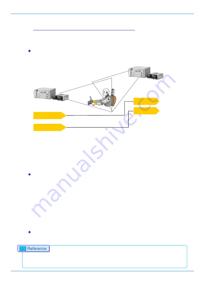
The system can perform synchronized recording by synchronizing multiple units using external
synchronization input/output.
Conceptual Diagram of Synchronous Connection
Synchronized recording settings using the system are made with the "remote controller (optional)"
or PFV. The conceptual settings when performing synchronized recording using two systems are
explained here. First, decide which camera to make the master camera (outputs the synchronization
signal) and the slave camera (receives the synchronization signal) from the two systems to use for
synchronized recording.
Setting the Master Camera (Outputs Synchronization)
Set the signal output for the master camera which will output the synchronization signal. Synchronization signal
settings are made with the PFV.
For PFV (Standard)
1.
Verify that the camera mode is in LIVE mode (the image displayed is passed through from the
camera). If the system is in a mode other than LIVE mode, check "Live" on the camera
control panel.
2.
Select I/O on the left tree from "Camera Option" on the camera control panel.
3.
Set "GENERAL OUT1".
Setting the Slave Camera (Receives the Synchronization Signal)
Next, set the synchronization signal input for the slave camera which will receive the synchronization signal
supplied by the master camera. Synchronization signal settings are made with PFV.
For the setting method of the signal inputted into GENERAL IN, refer to
SYNC OUT
SYNC IN
(MASTER)
(SLAVE)
CAMERA No.1
CAMERA No.2
(
BNC Cable)
Trig TTL OUT
Trig TTL IN
Содержание FASTCAM Multi
Страница 1: ...F FA AS ST TC CA AM M M Mu ul lt ti i ...
Страница 11: ......
Страница 14: ...7 1 Contact Information 66 ...
Страница 15: ...1 Chapter 1 Overview 1 1 Product Overview and Features ...
Страница 17: ...3 Chapter 2 Setup 2 1 System s Components and Accessories 2 2 Accessories Options 2 3 Part Names ...
Страница 40: ...Chapter 3 System Connections 26 ...
Страница 45: ...31 FASTCAM Multi Hardware Manual TRIG TTL IN GENERAL TTL IN TRIG SW IN SYNC IN Circuit Diagram ...
Страница 66: ...Chapter 4 Functions 52 ...
Страница 67: ...53 FASTCAM Multi Hardware Manual Chapter 5 Product Specification 5 1 Specifications 5 2 Dimensions ...
Страница 72: ...Chapter 5 Product Specification 58 5 2 2 Remote Controller Optional mm 167 9 105 4 155 4 28 2 29 7000 ...
Страница 73: ...59 FASTCAM Multi Hardware Manual 5 2 3 AC Adapter mm 130 2 188 4 223 218 2900 5 88 5 37 1 6 60 2 50 2 ...
Страница 75: ...61 FASTCAM Multi Hardware Manual 5 2 5 Clearance for Camera Cable Connection mm Minimum 275 ...
Страница 76: ...Chapter 5 Product Specification 62 ...
Страница 77: ...63 FASTCAM Multi Hardware Manual Chapter 6 Warranty 6 1 About the Warranty ...
Страница 79: ...65 FASTCAM Multi Hardware Manual Chapter 7 Contacting Photron 7 1 Contact Information ...


