


6 Hardware Interface
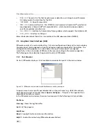
6.1.3
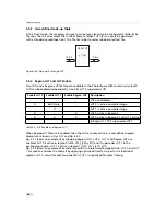
Trigger and Strobe Signals
The power connector contains an external trigger input and a strobe output.
The trigger input is equipped with a constant current diode which limits the
current of the optocoupler over a wide range of voltages. Trigger signals can
thus directly get connected with the input pin and there is no need for a current
limiting resistor, that depends with its value on the input voltage. The input
voltage to the
TRIGGER
pin must not 15V DC, to avoid damage to the
internal ESD protection and the optocoupler!
In order to use the strobe output, the internal optocoupler must be powered with 5 .. 15 V DC.
The
STROBE
signal is an open-collector output, therefore, the user must connect a pull-up
resistor (see Table 6.1) to
STROBE_VDD
(5 .. 15 V DC) as shown in Fig. 6.2. This resistor should be
located directly at the signal receiver.
Figure 6.2: Circuit for the trigger input signals
The maximum sink current of the
STROBE
pin is 8 mA.
Do not connect inductive
or capacitive loads
, such loads may result in damage of the optocoupler! If the
application requires this, please use voltage suppressor diodes in parallel with
this components to protect the optocoupler.
50
Содержание CameraLink MV1-D1280
Страница 1: ...User Manual Photonfocus MV1 D1280 CameraLink Series CMOS Area Scan Camera MAN058 05 2013 V1 1...
Страница 2: ......
Страница 4: ...2...
Страница 7: ...B Revision History 81 CONTENTS 5...
Страница 8: ...CONTENTS 6...
Страница 16: ...3 How to get started CameraLink Figure 3 4 PFRemote start window 14...
Страница 24: ...4 Product Specification 22...
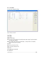
Страница 72: ...8 Graphical User Interface GUI 70...
Страница 74: ...9 Mechanical Considerations 72...
Страница 76: ...10 Warranty 74...
Страница 78: ...11 References 76...
Страница 82: ...A Pinouts 80...


