


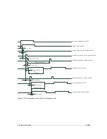


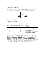


Sequential Read out Timing
The camera supports only the sequential read out timing. It means the exposure is started after
the read out of the previous frame (see Fig. 5.9).
The maximal frame rate is in this case (values are given in Table 5.5):
MaxFrameRate = 1 / (Exposu TRead ReadoutTime)
The ReadoutTime is the height of the ROI multiplied by the read out time of one row (see
Table 5.5).
T r i g g e r
E x p o s u r e
R e a d o u t
F r a m e < n >
F r a m e < n + 1 >
E x p o s u r e T i m e
R e a d o u t T i m e
T R e a d o u t D e l
Figure 5.9: Sequential read out timing
5.2
Trigger and Strobe
5.2.1
Introduction
The start of the exposure of the camera’s image sensor is controlled by the trigger. The trigger
can either be generated internally by the camera (free running trigger mode) or by an external
device (external trigger mode).
This section refers to the external trigger mode if not otherwise specified.
In external trigger mode, the trigger can be applied through the CameraLink
®
interface
(interface trigger) or directly by the power supply connector of the camera (I/O Trigger) (see
Section 5.2.2). The trigger signal can be configured to be active high or active low. When the
frequency of the incoming triggers is higher than the maximal frame rate of the current
camera settings, then some trigger pulses will be missed. A missed trigger counter counts these
events. This counter can be read out by the user.
An external trigger pulse starts the exposure of one image. In Burst Trigger Mode however, a
trigger pulse starts the exposure of a user defined number of images (see Section 5.2.5).
The start of the exposure is shortly after the active edge of the incoming trigger. An additional
trigger delay can be applied that delays the start of the exposure by a user defined time (see
Section 5.2.4). This often used to start the exposure after the trigger to a flash lighting source.
5.2.2
Trigger Source
The trigger signal can be configured to be active high or active low. One of the following
trigger sources can be used:
Free running
The trigger is generated internally by the camera. Exposure starts immediately
after the camera is ready and the maximal possible frame rate is attained, if Constant
Frame Rate mode is disabled. In Constant Frame Rate mode, exposure starts after a
user-specified time (Frame Time) has elapsed from the previous exposure start and
therefore the frame rate is set to a user defined value.
Interface Trigger
In the interface trigger mode, the trigger signal is applied to the camera by
the CameraLink
®
interface. Fig. 5.10 shows a diagram of the interface trigger setup. The
5.2 Trigger and Strobe
29
Содержание CameraLink MV1-D1280
Страница 1: ...User Manual Photonfocus MV1 D1280 CameraLink Series CMOS Area Scan Camera MAN058 05 2013 V1 1...
Страница 2: ......
Страница 4: ...2...
Страница 7: ...B Revision History 81 CONTENTS 5...
Страница 8: ...CONTENTS 6...
Страница 16: ...3 How to get started CameraLink Figure 3 4 PFRemote start window 14...
Страница 24: ...4 Product Specification 22...
Страница 72: ...8 Graphical User Interface GUI 70...
Страница 74: ...9 Mechanical Considerations 72...
Страница 76: ...10 Warranty 74...
Страница 78: ...11 References 76...
Страница 82: ...A Pinouts 80...


