


5 Functionality
trigger is generated by the frame grabber board and sent on the CC1 signal through the
CameraLink
®
interface. Some frame grabbers allow the connection external trigger
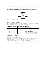
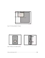
devices through an I/O card. A schematic diagram of this setup is shown in Fig. 5.11.
I/O Trigger
In the I/O trigger mode, the trigger signal is applied directly to the camera by the
power supply connector (via an optocoupler). A setup of this mode is shown in Fig. 5.12.
The electrical interface of the I/O trigger input and the strobe output is described in
Section 6.1.3.
C a m e r a
S y s t e m P C
M a c h i n e V i s i o n
B
A
D a t a C a m e r a L i n k
P o w e r
E X S Y N C ( C C 1 ) / S o f t t r i g g e r
C a m e r a L i n k
T M
F r a m e G r a b b e r
Figure 5.10: Interface trigger source
I / O B o a r d
C a m e r a 1
S y s t e m P C
M a c h i n e V i s i o n
B
A
D a t a C a m e r a L i n k
P o w e r
T r i g g e r S o u r c e
E X S Y N C ( C C 1 ) / S o f t t r i g g e r
C a m e r a L i n k
T M
F r a m e G r a b b e r
F l a s h
C a m e r a 2
D a t a C a m e r a L i n k
E X S Y N C ( C C 1 ) / S o f t t r i g g e r
P o w e r
Figure 5.11: Interface trigger with 2 cameras and frame grabber I/O card
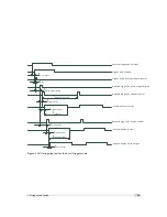
5.2.3
Trigger Timing
In the external trigger mode the rising edge of the trigger pulse starts the camera states
machine, which controls the sensor and optional an external strobe output. Fig. 5.13 shows the
30
Содержание CameraLink MV1-D1280
Страница 1: ...User Manual Photonfocus MV1 D1280 CameraLink Series CMOS Area Scan Camera MAN058 05 2013 V1 1...
Страница 2: ......
Страница 4: ...2...
Страница 7: ...B Revision History 81 CONTENTS 5...
Страница 8: ...CONTENTS 6...
Страница 16: ...3 How to get started CameraLink Figure 3 4 PFRemote start window 14...
Страница 24: ...4 Product Specification 22...
Страница 72: ...8 Graphical User Interface GUI 70...
Страница 74: ...9 Mechanical Considerations 72...
Страница 76: ...10 Warranty 74...
Страница 78: ...11 References 76...
Страница 82: ...A Pinouts 80...


