


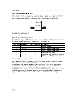


C a m e r a 1
F l a s h
T r i g g e r S o u r c e
T T L
T T L
S y s t e m P C
M a c h i n e V i s i o n
B
A
D a t a C a m e r a L i n k
P o w e r
C a m e r a L i n k
T M
F r a m e G r a b b e r
Figure 5.12: I/O trigger source
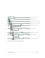
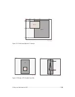
detailed timing diagram for the external trigger mode.
e x t e r n a l t r i g g e r p u l s e i n p u t
t r i g g e r a f t e r i s o l a t o r
t r i g g e r p u l s e i n t e r n a l c a m e r a c o n t r o l
d e l a y e d t r i g g e r f o r s h u t t e r c o n t r o l
i n t e r n a l s h u t t e r c o n t r o l
d e l a y e d t r i g g e r f o r s t r o b e c o n t r o l
i n t e r n a l s t r o b e c o n t r o l
e x t e r n a l s t r o b e p u l s e o u t p u t
t
d - i s o - i n p u t
t
j i t t e r
t
t r i g g e r - d e l a y
t
e x p o s u r e
t
s t r o b e - d e l a y
t
d - i s o - o u t p u t
t
s t r o b e - d u r a t i o n
t
t r i g g e r - o f f s e t
t
s t r o b e - o f f s e t
Figure 5.13: Trigger timing diagram
The rising edge of the trigger signal is detected in the camera control electronic which is
implemented in an FPGA. Before the trigger signal reaches the FPGA it is isolated from the
camera environment to allow robust integration of the camera into the vision system. In the
signal isolator the trigger signal is delayed by time t
d
−
iso
−
input
. This signal is clocked into the
FPGA which leads to a jitter of t
jitter
. The pulse can be delayed by the time t
trigger
−
delay
which
can be configured by a user defined value via camera software. The trigger offset delay
t
trigger
−
offset
results then from the synchronous design of the FPGA state machines and from to
requirement to start an exposure at a fixed point from the start of the read out of a row. The
exposure time t
exposure
is controlled with an internal exposure time controller.
5.2 Trigger and Strobe
31
Содержание CameraLink MV1-D1280
Страница 1: ...User Manual Photonfocus MV1 D1280 CameraLink Series CMOS Area Scan Camera MAN058 05 2013 V1 1...
Страница 2: ......
Страница 4: ...2...
Страница 7: ...B Revision History 81 CONTENTS 5...
Страница 8: ...CONTENTS 6...
Страница 16: ...3 How to get started CameraLink Figure 3 4 PFRemote start window 14...
Страница 24: ...4 Product Specification 22...
Страница 72: ...8 Graphical User Interface GUI 70...
Страница 74: ...9 Mechanical Considerations 72...
Страница 76: ...10 Warranty 74...
Страница 78: ...11 References 76...
Страница 82: ...A Pinouts 80...


