background image

IMS-4000 Manual

34

Battery Replacement

The IMS-4000 Node uses one (1) 6V 3.4AH rechargeable battery (included) for backup power in 
the event that main power fails. The unit will constantly recharge the battery whenever the power 
switch is turned on and the unit is plugged into a power supply.
In the event you need to replace the battery, be sure to use battery part # BAT-0006 (see Appendix 
C: Accessories) to ensure compatibility. 
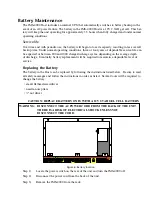
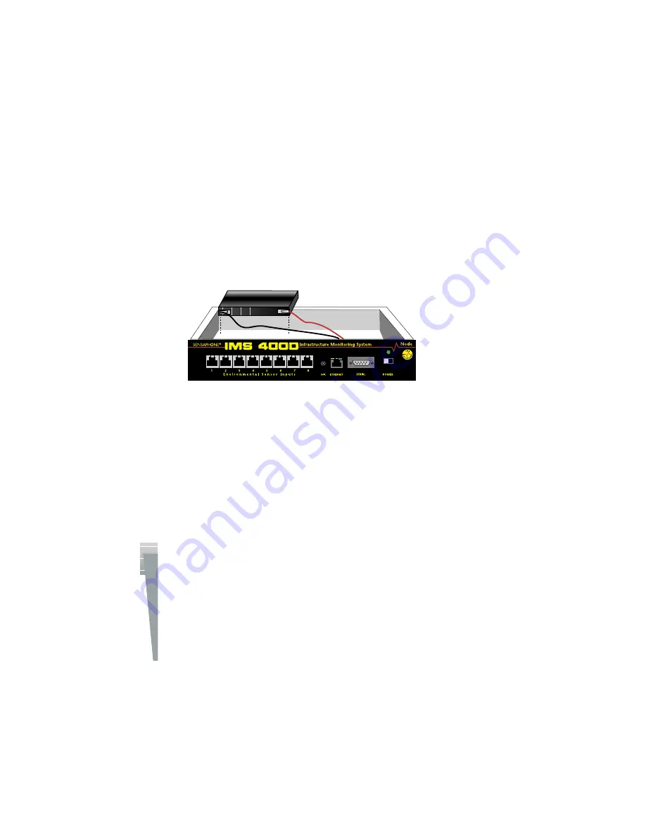
To install the new battery, first slide the power switch to the OFF position and disconnect the power 
adapter. Next, remove the top cover of the unit by removing the six screws using a small flat-head 
screwdriver. Remove the wire connectors from the old battery and replace it with the new one. 
Reconnect the wires to the new battery and reattach the top cover.

Note:

 Earlier versions of the Node used six (6) C-size 2000mAhr ni-cad batteries.  If you have 

one of these you must use C-size ni-cads to replace them.

Figure 8: Battery replacement in the Node unit

Rack Mount Installation

The IMS-4000 Node can be rack mounted using the included rack mount brackets.  Follow the 
steps below:

1) Attach rack-mount brackets to the Node with a Phillips screwdriver.
2) Attach the unit to the equipment rack using two pan-head screws per side.  Tighten the 

screws with a Phillips screwdriver.

3) Plug the power adapter into a power outlet.

Содержание Sensaphone IMS-4000

Страница 1: ...IMS 4000 User s Manual Version 2 4 8 PHONETICS INC SENSAPHONE ...

Страница 2: ...ot guarantee that changes in equipment made by other manufacturers and referred to in this manual will not affect the applicability of the information in this manual Copyright 2003 by Phonetics Inc Second Edition version 2 4 8 May 2005 Written and produced by Phonetics Inc Please address comments on this publication to Phonetics Inc 901 Tryens Road Aston PA 19014 Sensaphone is a registered tradema...

Страница 3: ...n it to Sensaphone Customer Service or another approved repair facility when any service or repair work is required Opening or removing covers may expose you to dangerous voltages or other risks Incorrect reassembly can cause electric shock when the unit is subsequently used If anything happens that indicates that your IMS 4000 is not working properly or has been damaged unplug it immediately and ...

Страница 4: ...ey will notify you in advance But if advance notice isn t practical the telephone company may temporarily discontinue service without notice and you will be notified as soon as possible You will be informed of your right to file a complaint with the FCC The telephone company may make changes in its facilities equipment operations or procedures where such action is reasonably required in the operat...

Страница 5: ...nts The Department does not guarantee the equipment will operate to the user s satisfaction Before installing this equipment users should ensure that it is permissible to be connected to the facili ties of the local telecommunications company The equipment must also be installed using an accept able method of connection In some cases the company s inside wiring associated with a single line indivi...

Страница 6: ...tions relating to WBMP copyright 2000 2001 2002 Maurice Szmurlo and Johan Van den Brande Permission has been granted to copy distribute and modify gd in any context without fee including a commercial application provided that this notice is present in user accessible supporting documenta tion This does not affect your ownership of the derived work itself and the intent is to assure proper credit f...

Страница 7: ...ARRANTY LIMITATION OF DAMAGES AND DISCLAIMER OF LIABILITY FOR DAMAGES THE WARRANTOR S OBLIGATION UNDER THIS WARRANTY IS LIMITED TO REPAIR OR REPLACEMENT OF THE PRODUCT AT THE WARRANTOR S OPTION AS TO REPAIR OR REPLACEMENT IN NO EVENT SHALL WARRANTORS BE LIABLE OR RESPONSIBLE FOR PAYMENT OF ANY INCIDENTAL CONSEQUENTIAL SPECIAL AND OR PUNITIVE DAMAGES OF ANY KIND INCLUDING BUT NOT LIMITED TO ANY LAB...

Страница 8: ...nse Agreement or other Agreement provided by Warrantors to purchaser The agreement between the Warrantors and the Purchaser including but not limited to the terms and conditions herein shall not be governed by the Convention for the International Sale of Goods Where applicable the Uniform Commercial Code as adopted by the State of Delaware shall apply 4 PROCEDURE FOR OBTAINING PERFORMANCE OF WARRA...

Страница 9: ... This Manual 20 HOST INSTALLATION and CONFIGURATION 20 Physical Description 20 Front Panel Layout 20 Serial Port 20 RJ 45 10 100BASE T Ethernet Port 20 Phone Jack 21 Sensor Inputs 21 Sensor Input LEDs 21 AC Power and Battery LEDs 22 Microphone Jack 22 Rear Panel 22 ON OFF Switch 22 Installation 22 Parts Required 22 Operating Environment 23 Rack Mount Installation 23 Wall Mount Installation 23 Tabl...

Страница 10: ...tery Replacement 34 Rack Mount Installation 34 Wall Mount Installation 34 Tabletop Installation 35 Connecting Sensors 35 Network Configuration 36 Local Configuration Definitions 37 Node Specifications 38 Operating Specifications 38 Communications Specifications 38 Environmental Monitoring 38 Chapter 2 IMS 4000 Software 39 Introduction 39 Help 39 IMS 4000 Quick Start Guide 39 Install Units and Conf...

Страница 11: ...necting to a Host 44 Deleting a Host 44 Setting the Unit Properties for the IMS Host 45 Adding a Node 46 Deleting a Node 47 Changing Host Network Settings using ConsoleView 47 Setting the Unit Properties for the Node 47 Sample Application 48 Changing Node Network Settings 48 Configuring Environmental Inputs 49 Channel Setup 49 Alarm Response via the PowerGate PowerGate2 or Camera 52 PowerGate 52 C...

Страница 12: ...m Delivery Options 66 Saving and Loading Programming 67 Reconnecting 67 Recording and Uploading Voice Messages 67 Recording Voice Messages 68 Holiday Setup 69 Alarm Message Pop Ups 70 Activating Alarm Pop Ups 70 Enabling Custom Pop Up Messages 71 Setting Pop Up Text Location 71 Editing Pop Up Custom Message 71 Audible Alarm Notification 72 E Mail Setup and Two Way E Mail Commands 72 SMTP Error mes...

Страница 13: ...ally Forcing History Downloads 84 Updating Firmware 84 Chapter 3 Operation 85 Alarm Delivery and Acknowledgment 85 Alarm Acknowledgment 85 Alarm Delivery Logic 86 Sample Alarm Messages 86 Sample E mail alarm message 86 Sample Fax message 87 Sample Alphanumeric Pager Message 87 Voice Status Report and Touch Tone Commands 87 User Specific Reports 87 Sample Status Report 88 Voice Alarm Dialout 88 Per...

Страница 14: ... Software 96 Switching Outlets using the IMS ConsoleView Software 97 Automatic Outlet Switching 97 Switching Outlets via Telephone 97 Switching Outlets via Email 97 IMS PowerGate Specifications 98 Chapter 6 PowerGate2 99 Physical Description 99 Front Panel Layout 99 Rear Panel 99 LEDs 99 Installation 100 Parts Required 100 Operating Environment 100 Rack Mount Installation 100 Wall Mount Installati...

Страница 15: ...urface installation 108 Configuration 109 Fahrenheit Celsius Selection 109 Sensor Template factory default 110 Specifications 110 IMS 4811 Room Temperature Sensor with display FAHRENHEIT 111 Installation Instructions 111 Introduction 111 Package Contents 111 Cabling 111 Mounting 111 Electrical box installation 111 Hidden cable surface installation 112 Visible cable surface installation 112 Configu...

Страница 16: ...19 Electrical box installation 119 Hidden cable surface installation 120 Visible cable surface installation 120 Configuration 121 Sensor Template factory default 121 Specifications 121 IMS 4821 Room Humidity Sensor with display 122 Installation Instructions 122 Introduction 122 Cabling 122 Mounting 122 Electrical box installation 122 Hidden cable surface installation 123 Visible cable surface inst...

Страница 17: ...lation Instructions 131 Introduction 131 Package Contents 131 Wiring the Contact 131 Cabling 131 Mounting 132 Configuration 132 Sensor Template factory default 133 Specifications 133 IMS 4851 4 20mA Bridge 134 Installation Instructions 134 Introduction 134 Package Contents 134 Wiring the Transducer 134 Cabling 134 Mounting 135 Configuration 135 Host and Node Firmware Requirements 136 IMS 4000 Host...

Страница 18: ...sor Template factory default 142 Specifications 142 IMS 4862 Smoke Detector Sensor 143 Installation Instructions 143 Introduction 143 Cabling 143 Mounting 143 Configuration 143 Sensor Template factory default 144 Specifications 144 Technical Support for the IMS 4000 Sensors 145 Appendix A Weekly Testing Procedure 147 Appendix B Troubleshooting 149 Appendix C IMS 4000 Accessories 151 Appendix D Lic...

Страница 19: ...gnostic tests via Touch Tone commands or e mail And with the IMS 4000 PowerGate you can also remotely reboot equipment Features The IMS 4000 series of products includes the following key features n Expandable architecture permitting up to thirty one IMS 4000 Nodes to be used with each IMS 4000 Host n Eight sensor inputs per Host to monitor environmental conditions and or alarm contacts from other ...

Страница 20: ...yout The front panel contains connections for eight sensor inputs microphone input Ethernet port serial port and status LEDs See figure below Figure 1 Front Panel Layout of the IMS 4000 Host 1 Serial Port 2 Ethernet port 10 100Base T 3 Phone line 4 Sensor Inputs 8 5 Battery Power Alarm LED 6 AC Power Alarm LED 7 External Microphone Input 8 Internal Microphone Serial Port The RS 232 serial port is ...

Страница 21: ...hen installing or modifying telephone lines Sensor Inputs The sensor inputs are designed to interface with IMS 4000 series sensors See Chapter 6 The use of RJ 45 jacks for sensor inputs allows the use of existing structured cabling to connect remote sen sors Since the sensor produces an analog signal it must connect directly to the Host or Node The path from the sensor to the IMS unit CANNOT pass ...

Страница 22: ...tectors When an external microphone is connected the internal microphone is disabled Rear Panel The rear panel is where the main power switch is located The main power cord attaches to the IEC320 connector The unit can be powered from 90 260VAC 47 63Hz ON OFF Switch The on off switch connects main power and battery power to the system Note that the system will only turn on when main power is prese...

Страница 23: ...ment Operating Temperature 32º 122º Fahrenheit 0º 50º C Humidity 5 90 RH non condensing Power 90 260VAC 47 63 Hz outlet within 6 Rack Requirements Standard 19 equipment rack with supplied mounting bracket hardware Requires 1 0 EIA rack mount space Tabletop requirements Flat area which can support an enclosure 17 wide by 10 deep by 2 high Rack Mount Installation A S EG ...

Страница 24: ...tion The IMS 4000 Host can be installed on a tabletop or shelf Follow the steps below 1 Attach the four self adhesive rubber feet to the four corners on the bottom of the IMS 4000 2 Place the unit on a tabletop or shelf and connect the power cord into a 90 260VAC outlet ...

Страница 25: ...DTE so you will need to use a null modem cable Terminal communication settings must be set to n 9600 baud no parity 8 data bits 1 stop bit To get online with the IMS 4000 connect your terminal to the serial port and press RETURN A menu will appear which will guide you through the setup Sensaphone IMS 4000 Host Unit V1 0 0 0 Enter Password The DEFAULT PASSWORD for a New Unit is ims4k 1 Display Ente...

Страница 26: ...ty private SNMP Agent Enabled Allow remote configuration Disabled Press any key to return to main menu Option 3 will allow you to set all pertinent network settings listed under Option 2 NOTE You can remotely reconfigure the Host network settings using the IMS 4000 ConsoleView software if the Allow Remote Configuration option is set to Y However the Host must initially be configured via the serial...

Страница 27: ...ord ims4k This temporary account will unload if any one of the following occurs 1 Any of the Master Administrator accounts is edited 2 A new Master Administrator account is created or 3 The system reboots Option 0 allows you to disable all inbound modem communications This feature is provided for users who cannot have a device with a modem connected to their network Option A allows you to program ...

Страница 28: ...at will transfer TCP IP data in and out of your LAN A single LAN that is not connected to other LANs does not require a gateway setting DNS The DNS server is used to translate site names into actual numeric network addresses Enter the IP address of the DNS server for your network Enable Web Setting this to Y will enable the web page feature of the IMS 4000 Set this to N if you do not want the unit...

Страница 29: ...ending on the average depth of discharge Eventually battery replacement will be required to maintain a dependable level of service Replacing the Battery The battery in the Host can be replaced by following the instructions listed below Be sure to read all safety messages and follow the instructions in order as listed Several tools will be required to change the battery small flathead screwdriver n...

Страница 30: ...ctor with the red wire from the battery Step 7 Using the nut driver remove the four nuts which hold down the battery bracket Remove the bracket and battery Step 8 Install the new battery and replace the bracket Step 9 Attach the connector with the red wire to the positive terminal of the battery Step 10 Attach the connector with the black wire to the negative terminal of the battery Step 11 Replac...

Страница 31: ...up Battery 12V 2 9AH Sealed Gel Cell Backup Time 3 5 Hours Ethernet 10 100 Base T 10 100Mbps RS 232 DB9 9600bps DTE Modem 33 6Kbps Fax Group 3 14 4Kbps Voice Processor Yes Internal Monitoring AC Power True RMS Voltage Backup Battery Level Sound Level in dB Number of Sensor Ports 8 Sensor Types Temperature Humidity Water Power Infrared Motion Smoke Dry Contacts Sensor Input Connector RJ 45 Sensor C...

Страница 32: ...uts allows the use of existing structured cabling to connect remote sensors Microphone The Node unit comes with a built in microphone Directly below the built in mic is a separate jack for connecting an optional condenser microphone to sense audible alarms such as smoke detectors When an external microphone is connected the internal microphone is disabled RJ 45 10 100BASE T Ethernet Port This jack...

Страница 33: ... units can be identified by their black network jack or via software they will be running firmware version 2 xx or earlier Installation This section provides information on n Operating environment n Rack wall tabletop installation n Connecting sensors n Replacing batteries Parts Required Phillips DB9 F F null Dumb terminal or PC Screwdriver modem cable w DB9 serial port Operating Environment Befor...

Страница 34: ...nit by removing the six screws using a small flat head screwdriver Remove the wire connectors from the old battery and replace it with the new one Reconnect the wires to the new battery and reattach the top cover Note Earlier versions of the Node used six 6 C size 2000mAhr ni cad batteries If you have one of these you must use C size ni cads to replace them Figure 8 Battery replacement in the Node...

Страница 35: ...ach the unit to the wall using two screws per side Tighten the screws with a Phillips screwdriver 4 Plug the power cord into a 120VAC 60Hz outlet NOTE An international version is available for 220V 50Hz operation Order part IMS 4003 ...

Страница 36: ... the configuration The port is male DTE so a DB9 female female null modem cable will be required Terminal communication settings must be set to n 9600 baud no parity 8 data bits 1 stop bit no flow control To get online with the IMS 4000 Node connect your terminal to the serial port and press RETURN A menu will appear which will guide you through the setup Sensaphone IMS Node Unit Version 2 38 Main...

Страница 37: ...This is the IP address of the IMS 4000 Host that this Node is associated with Node IP Address This is the IP address assigned to the IMS 4000 on your network This address is provided by you or your network administrator It is formatted as a standard dotted decimal number Subnet Mask This is the subnet mask which distinguishes the portion of the IP address that is the network ID from the portion th...

Страница 38: ... h x 7 0 d x 9 6 w Backup Battery 1 6V 3 4AH sealed rechargeable Backup Time 3 5 Hours Ethernet 10 100 Base T 10 100Mbps RS 232 DB9 9600bps DTE Internal Monitoring AC Power Backup Battery Level Sound Level in dB Number of Sensor Ports 8 Sensor Types Temperature Humidity Water Power Infrared Motion Smoke Dry Contacts Sensor Input Connector RJ 45 Sensor Cables CAT 5 568B Cable Length 1000 External M...

Страница 39: ...on the front of the units A terminal or terminal emulation program can be used Set the terminal set tings for 9600bps 8 N 1 The default password is ims4k Install Software and Log In to Host Install the IMS 4000 software from your CD ROM or other media Double click on the IMS 4000 icon on your desktop The IMS 4000 ConsoleView screen will appear From the main menu select Enterprise then Add Enterpri...

Страница 40: ...amount of programming required to set up your sen sors To configure the Templates click the plus box next to the word Settings to expand the options under this heading Next expand the Input Templates This will list all of the different sensor types Right click on each of the sensor names to bring up the individual Template programming screens An example is shown below Figure 2 Default Input Channe...

Страница 41: ...oice messages can be used to identify your IMS Hosts Nodes PowerGates Input sen sors IP alarms and PowerGate outlets Voice messages must first be recorded on your computer and then uploaded to the IMS Host Use the CustomVoice Manager screen to record and upload your voice messages To access the CustomVoice Manager screen expand the Host menu and select Voice Note that Voice messages should be reco...

Страница 42: ...es installation quick and easy Make sure that all Windows applications are closed before attempting to run setup If you encounter problems during installation please call Sensaphone Technical Support at 610 558 2700 Installing from the CD 1 Start Windows 2 Insert IMS 4000 CD ROM 3 Select Start Run and type in D Setup exe and click OK Note If your CD ROM is installed on a drive letter other than D ...

Страница 43: ...ost through a dialup connection be sure to establish a PPP connection before running the software See Remote Login via Dialup See the sections in your Host and Node Manuals on Local Configuration To get started double click on the IMS 4000 software icon This will bring up the IMS ConsoleView Screen Figure 6 IMS ConsoleView screen Adding an Enterprise Group From the ConsoleView menu click on Enterp...

Страница 44: ......

Страница 45: ...stom voice messages can be recorded and uploaded to the Host on the Custom Voice Manager screen The Host Custom Voice message is the first message spoken during a voice call This message should describe the name and location where the Host is installed Enter the number of Dialout Attempts you want the IMS to make when an alarm occurs Dialout attempts is the number of times the IMS will try to call...

Страница 46: ...ion If you would like the unit to synchronize its time on a daily basis enter the IP address of a compatible time server Figure 11 Clock settings tab The IMS 4000 can be programmed to synchronize its clock to a reference time server every night at midnight To use this feature the IMS 4000 must have network access to a server which supports one of the following time code protocols Network Time Prot...

Страница 47: ...ings The first tab is titled Ethernet Settings click the Modify button to bring up the Network Setup screen Figure 13 Host Network Settings NOTE If the Modify button is grey inactive then the unit either does not have the Allow Remote Configuration option set or the unit s firmware does not support this feature and requires upgrading Enter the new network parameters and click OK A warning message ...

Страница 48: ...traffic generated by Node to Host communication but want to view input values that are no more than 20 minutes old You can enable the Auto Send option and enter an interval of 1200 seconds 20 minutes This will limit Node to Host data transfers to no more than 700 bytes every 20 minutes 2 Suppose that in addition if the temperature changes by more than 3 degrees Fahrenheit about 4 at room temperatu...

Страница 49: ...ntal Inputs Each host or node can have up to 8 external sensors connected The host or node will automatically identify what sensor type is connected to each input To program the environmental input param eters expand the host or node tree by clicking the plus box next to the host node name Channel Setup Next click in the plus box beside Environmentals to expand the tree below it Choose the input y...

Страница 50: ... monitoring If it is disabled the IMS 4000 will not send alarm messages A channel can be enabled or disabled based on a 7 day holiday time schedule Schedule Click this button to bring up the Edit Schedule screen This screen allows you to set times when the channel is enabled or disabled The blue line indicates days times when the channel is enabled Figure 18 Sensor Schedule screen The schedule exa...

Страница 51: ...creen Figure 19 Alarm Class dropdown menu Custom Voice Click the drop down arrow and select the custom voice message you would like assigned to this sensor channel Voice messages can be recorded on your PC and uploaded into the IMS 4000 on the Custom Voice Manager screen See Recording and Uploading Voice Messages Figure 20 Custom Voice dropdown menu Wait Recognition Time This is the time required ...

Страница 52: ...n to add this response to the list of current responses click Delete to remove an action Repeat for as many outlets as you wish to program Camera Snapshots on Alarm Camera images may be sent to one or more users when an Environmental or IP alarm occurs Up to four alarm responses PowerGate or Camera Snapshot may be programmed per input To con figure this feature choose Alarm Response from the Prope...

Страница 53: ...er of decibels On the High Sound programming screen this parameter is listed as Change in dB The default setting is 30db This means that if the audio level increases more than 30 dB for the dura tion of the recognition time an alarm will be tripped To verify that your audible alarm is capable of tripping an alarm we recommend that you perform several tests to check the decibel increase at the IMS ...

Страница 54: ...larms The IMS 4000 monitors the presence of all connected sensors to insure the reliability of the system When a sensor is removed from a Host or Node for more than a minute a trouble alarm is gener ated All trouble alarms are a part of the Diagnostic class so any User who wishes to receive sen sor Trouble Alarm System Diagnostic or Fault Alarms can do so by including the Diagnostic class in their...

Страница 55: ...ns under this heading Next expand the Input Templates This will list all of the different sensor types Figure 24 Template Types Right click on each of the sensor names to bring up the individual Template programming screens An example is shown below Figure 25 Template Chapter 2 Software 55 ...

Страница 56: ...ords the monitored IP address is dependent upon the Dependency IP address to function Alarm is Enabled Unchecking this box will disable the IP alarm Add to Datalog Click this box to store the value or status of the channel in the datalogger Last Response This is the date time that the IP device last responded Last Alarm This is the date time that the last IP alarm occurred for this IP address Last...

Страница 57: ...ass Click the drop down arrow and select the appropriate class for this type of alarm If you prefer you can create your own classes on the Class Setup screen to group certain types of alarms Custom Voice Click the drop down arrow and select the custom voice message you would like assigned to this IP Alarm Voice messages can be recorded on your PC and uploaded into the IMS 4000 on the Voice screen ...

Страница 58: ...dency device returns to normal e g starts responding to ping connect requests When an IP Alarm s dependency is not responding the status for the IP Alarm will be shown as IP route down It is recommended that the dependency device be programmed such that it will go into alarm before any other devices You can achieve this by setting the number of Retries for the dependency device to a lower value th...

Страница 59: ......

Страница 60: ......

Страница 61: ...llowing screen will appear Figure 30 User Profile screen The Name Company Department and Title information are used to identify the user on reports that the unit sends The Username Password and User Code are used for security purposes You must have a Username and Password to go online with the unit request two way e mail features access other features of the unit The User Code is a four digit numb...

Страница 62: ...rties Yes No No Edit e mail settings Yes No No Edit Node properties Yes No No Update firmware Yes No No Configure data logger Yes No No Add delete classes Yes No No Add delete holidays Yes No No Edit default input templates Yes No No Delete sensors Yes Yes No Disable IP alarms Yes Yes No Reset min max Yes Yes No Other programming changes Yes Yes No Add camera Yes Yes No Acknowledge alarms Yes Yes ...

Страница 63: ...eive information or send commands if they have the proper permissions and Class associa tions Examples 1 If a User that has no Permissions on a particular Node then the user will not be able to receive any Voice or e mail reports that contain information about that Node 2 If a User has permissions on a particular Host Node unit but none of the environmental sensors are in his class then he will no...

Страница 64: ...an be changed at any time To move a Contact up or down in the list click and hold the Contact you wish to move and drag it to its new location then release the mouse button The Contact should now display in its new location Adding Contacts To add a Contact right click on the User Profile you wish to add a contact to and select Add New Contact An entry called New Contact will appear below the User ...

Страница 65: ...ll be dialed after the auto attendant answers Numeric Pager Calls The IMS 4000 can send alarm messages to numeric pagers It will automatically send its ID tele phone number when dialing to a numeric pager All you have to do is enter the telephone number of your pager Be sure to include the area code or 1 area code as necessary Example 301 565 2300 If your pager service is answered by a voice promp...

Страница 66: ...ble specific hours days Alarm Delivery Options There are additional options which appear on the Contact Setup screen depending upon the type of call For alarm delivery you must select either Receives Unacknowledged Alarms or Receives Inform Only Alarms or both Receives Unacknowledged Alarms This option applies only to voice and pager calls When select ed the IMS 4000 will call this contact until t...

Страница 67: ...PC and IMS 4000 Host units may become disconnected This may happen due to a system restart or other communication related problem You can reconnect to an IMS 4000 using the Reconnect command To reconnect to a unit click on File from the main menu and select Reconnect Highlight the IP address of the unit you want to reconnect with and then click the Reconnect button Figure 35 Reconnect Screen Recor...

Страница 68: ...ch screen until you get back to the Sound Recorder main screen To record a message click the button with the Red circle To play a message click the right arrow Play button Trim off any silence before and after the message to ensure that the voice report flows smoothly Messages can be trimmed by sliding the message position bar and selecting Edit from the main menu and then either Delete Before Mes...

Страница 69: ...rom one IMS 4000 Host to another Holiday Setup The IMS 4000 allows you to program recurring or non recurring holidays that you can use within your schedule programming These schedules are used to enable or disable monitoring of Environmental and IP Alarms and also to enable disable times when users will receive alarm calls To see which holidays are currently programmed expand the Settings menu by ...

Страница 70: ...s can be stored either on the local workstation or a drive that is regularly mapped to the workstation Activating Alarm Pop Ups Click on File then Options from the main menu in the ConsoleView Software The following screen will appear Figure 41 Options Screen Within the section titled Alarm Notification click in the box to Enable Alarm Pop Up Notifications This will activate the Alarm Message Pop ...

Страница 71: ...e the messages will be stored Editing Pop Up Custom Message To edit the custom message for a particular environmental input or IP alarm right click on the cho sen input and select Edit Alarm Pop Up Message The following screen will appear Figure 43 Edit Popup Screen Messages can be displayed as text or HTML Select the type of message you want to enter and type your message into the text area This ...

Страница 72: ...t click on the Host name and select Network Settings Select the Email Settings tab to see the following screen Figure 46 E mail Settings tab To have the unit send e mail you need to set the SMTP Server name and the Return e mail Address Username if required and Password if required To have the unit respond to Two Way e mail commands you must also set the POP Server name e mail account Username Pas...

Страница 73: ...ts on a PowerGate Note Two way e mail is dependent upon User permissions This means that the user can only receive information on items for which he has permission See Permissions section In order to have the IMS respond to e mail commands you must first obtain an e mail address for your IMS 4000 from your internet provider configure the e mail settings for your IMS Host see e mail setup and have ...

Страница 74: ...e Name Outlet Name on off cycle For example To ims4000 mycompany com Subject ims4000 username jsmith email jsmith555 aardvark net command powergate Gear Rack 1 Netgear switch 3 cycle Requesting a Picture from a Camera You can receive an e mail with an attached picture from any camera configured in the IMS 4000 The picture will be captured when the IMS 4000 receives the e mail request To receive a ...

Страница 75: ... are all network video cameras that allow you to view live streaming video or capture images to e mail when an alarm occurs The camera or server connects to your network via an RJ 45 jack and supports 10 100 Mbit networks Up to 128 cameras or servers may be associated with each Host or Node The IMS 4000 ConsoleView Software allows you easily to click and view live video wherever your camera is ins...

Страница 76: ... associate a camera with more than one device if desired To associate one or more cameras right click on Cameras within the menu tree for the selected host or node See screen sample below Figure 48 Associating Cameras The window on the left lists all cameras programmed into the system The window on the right lists cameras associated with the selected Host or Node To move a single camera to the oth...

Страница 77: ...an also be password protected You can program most parameters through the web page if the Web Page Programming option is enabled This can be secured with the same permissions options as with the ConsoleView software To gain access to the programming screens you must log in on the web page To view the Web Page simply type in the Host s IP address in your web browser Graphs Anything you are data log...

Страница 78: ...heck the Automatic Refresh box and enter the number in seconds between updates in the Update Every box Figure 51 Web Page Refresh Enabled Remote Web Page The IMS 4000 can send a copy of its web page to another web server via FTP File Transfer Protocol so that the web page can be viewed on another network for example on the Internet To configure the unit to FTP the web page right click on the Host ...

Страница 79: ... within the web site where the pages will upload Username Your user name for your web account Password The log in password you need to access the folders and files in your web account Update Interval This time period determines how often the web page is uploaded Create HTML as This is the file name given to your web page Create WML as This is the file name given to web pages to be viewed with wire...

Страница 80: ... many users it may be advantageous to store the database on a network drive To specify the drive for saving History information click File then Options from the main menu A sample screen is shown below Figure 53 History Options To change the location for storing the History database click the folder button on the right side of the screen and choose a new location The location you select will be di...

Страница 81: ...software in two ways There is the quick view which can be displayed by right clicking on an input or profile and selecting History or you can perform a query on the entire history database using the HistoryView program right click on History in the menu tree and select HistoryView or from the main menu select File then HistoryView History QuickView You can display a quick view of an input or profi...

Страница 82: ... the listed items will become selected and or deselected Last select a time frame to perform the query and click View The selected data will now be displayed See sample screen below Figure 56 History Viewer Graphing Graphing data is possible when the selected query contains only Samples If you click on the Graph button all of the points in the query will be displayed as a line graph There are also...

Страница 83: ...t Archiving As the history database grows it will begin to take longer to perform a query It is recommended that the database be periodically archived to keep the size reasonable and to permit satisfactory performance of the HistoryView program Archiving may be done as often as necessary for perfor mance reasons but it must be done when the database reaches its physical limit To find out how big t...

Страница 84: ...dates will be included as part of a complete IMS 4000 installation upgrade Check the IMS 4000 website www sensaphone com support 4000 html for the latest information on updates If you register your unit you will always be informed of the latest features enhancements and corrections To check the version of Firmware in your IMS 4000 right click on the Hostname and select Version Info The following s...

Страница 85: ... and once acknowledgement is received this user is removed from the list If a user always wants to be contacted when an alarm occurs we call this contact type Inform Only This means that this user will always receive notification of the alarm regardless of acknowledgement by other users Alarm Acknowledgment Alarms can be acknowledged six ways 1 By entering your Usercode using a touch tone telephon...

Страница 86: ...e that alarms can only be acknowledged during a voice call or by logging in via the IMS Consoleview Software If there are NO calls of the Unacknowledged type then the IMS 4000 will acknowl edge the alarm immediately after starting the alarm delivery process It is not recommended that you set pager calls to Unacknowledged unless there are also voice calls being made the reason being that the only m...

Страница 87: ...tatus report when called via telephone The status report can provide information on both environmental conditions and IP alarms In addition you can ping devices over the telephone and switch PowerGate outlets User Specific Reports The status report is customized based on your User Code Only callers with a valid User Code can hear a Status Report Alternatively the unit is also capable of matching t...

Страница 88: ...ted below Items in italics are custom messages recorded by the user Environmental sensors at the IT Dept of XYZ Company Channel 1 temperature in the server room is 76 4 degrees Fahrenheit OK Channel 2 temperature in rack B is 82 7 degrees Fahrenheit too high Channel 3 humidity in the server room is 33 9 OK Channel 6 water under server room floor OK Channel 7 smoke alarm in the server room OK Chann...

Страница 89: ...sage on your pager or in your voice mail you can still acknowledge the alarm by calling the unit back and entering your User Code Note that the Intercall Delay must be set to at least 1 minute in order for the unit to answer a call When you call in to the unit wait for the beep and then press a button on your touch tone tele phone If there are unacknowledged alarms in the User s class the unit wil...

Страница 90: ... If Dialup Networking is not listed it may not be installed on your computer in which case you will need to use your Windows installation CD to add it Windows XP To configure Dial up Networking double click on My Computer then select My Network Places then View Network Connections Select Create a New Connection or click on the Start button then Programs Accessories Communications New Connection Wi...

Страница 91: ... IMS 4000 items that can be fully accessed through SNMP Edit Environmental input programming Edit IP Alarm programming Edit System programming unit info e mail setup Web FTP setup phone settings Enable Disable Datalogging Edit the Datalog interval Edit add Classes Edit Environmental input template programming Edit Camera setup Edit PowerGate programming and switch outlets Acknowledge alarms View N...

Страница 92: ...are some examples of the more common OIDs in the IMS 4000 Name iso org dod internet private enterprises sensaphone Sensaphone OID 1 3 6 1 4 1 8338 Host Environmental Input Values 1 3 6 1 4 1 8338 1 1 1 1 8 1 1 7 input number Example host environmental input 3 1 3 6 1 4 1 8338 1 1 1 1 8 1 1 7 3 Node Environmental Input Values 1 3 6 1 4 1 8338 1 1 1 N 1 8 1 1 7 input number where N is the node numbe...

Страница 93: ...cal Description The IMS 4000 PowerGate is housed in a 17 w x 1 75 h x 10 d enclosure which is 1 EIA rack mount space high Front Panel Layout The front panel contains a 15 Amp breaker Output LEDs the serial port and power indicator See figure below ...

Страница 94: ...nts Standard 19 equipment rack with supplied mounting bracket hardware Requires 1 0 EIA rack mount space Tabletop requirements Flat area which can support an enclosure 17 wide by 10 deep by 2 high Rack Mount Installation The IMS 4301 PowerGate can be rack mounted using the included rack mount brackets Follow the steps below 1 Attach the rack mount brackets to the PowerGate with a Phillips screwdri...

Страница 95: ...r shelf and connect the power cord into a 120VAC outlet Figure 5 Tabletop mounted PowerGate Unit Connection to IMS 4000 Host or Node The PowerGate connects to an IMS 4000 Host or Node using the 9 pin null modem cable includ ed Connect the cable to the RS 232 port on the PowerGate and connect the other end to the RS 232 port on the Host or Node The PowerGate will automatically be recognized by the ...

Страница 96: ...e will automatically be recognized by the IMS Host or Node Within the IMS tree structure an entry called PowerGate will appear within the submenu of the Host and or Node To expand the Host or Node submenus you must click the box with the plus sign next to the appropri ate Host or Node The figure below shows the menu location of a PowerGate connected to a Host Figure 7 PowerGate in Hierarchy To ass...

Страница 97: ...e outlet will be switched Off for 10 seconds and then will automatically switch back On When you select Off or Cycle an addi tional prompt appears to confirm that you really want to remove power from the selected device Note that the PowerGate will switch each outlet after a short delay but the PowerGate2 will switch all selected outlets simultaneously Figure 9 Switching Outlets Automatic Outlet S...

Страница 98: ...Operating Specifications IMS 4000 Manual 98 Temperature 32 122 F Humidity 5 90 RH non condensing Power Supply 120VAC 60Hz Current Consumption 100mA output load Over Current Protection 15A Breaker Dimensions 1 8 h x 10 0 d x 17 3 w ...

Страница 99: ...is housed in a 17 5 w x 1 75 h x 12 3 d enclosure which is 1 EIA rack mount space high Front Panel Layout The front panel contains eight power inputs corresponding to the eight outlets on the rear eight 15 Amp breakers power LEDs a serial port and one power indicator LED See figure below ...

Страница 100: ... non condensing Power 120VAC 60 Hz outlet within 6 Multiple 15A 120VAC outlets for powering equipment Rack Requirements Standard 19 equipment rack with supplied mounting bracket hardware Requires 1 0 EIA rack mount space Tabletop requirements Flat area which can support an enclosure 17 wide by 10 deep by 2 high Rack Mount Installation The IMS 4302 PowerGate2 can be rack mounted using the included ...

Страница 101: ...teps below 1 Attach the optional wall mount brackets to the sides of the IMS 4302 using the eight black 6 32 screws A Phillips screwdriver will be required Order part IMS 4501 Universal Wall Mount Kit 2 Attach the unit to the wall using two screws per side Tighten the screws with a Phillips screwdriver 3 Plug the power cord into a 120VAC outlet ...

Страница 102: ......

Страница 103: ...n if main power to the unit is removed This allows you to pass power from a UPS through the PowerGate2 to your equipment without worrying about the PowerGate2 losing power PowerGate2 Setup via the IMS ConsoleView Software The PowerGate2 will automatically be recognized by the IMS Host or Node Within the IMS tree structure an entry called PowerGate2 will appear within the submenu of the Host and or...

Страница 104: ...t 5 is selected Multiple outlets can be switched at the same time by holding down either the Shift key select a continuous block or the Control Key to select a discontinuous assortment of outlets After making your selections click the On Off or Cycle but ton to execute the command When Cycle is selected the outlet will be switched Off for 10 seconds and then will automatically switch back On When ...

Страница 105: ...tal or IP alarm occurs Up to eight actions can be applied for each alarm response The PowerGate2 will perform all automated switching simultaneously See Configuring Environmental Inputs and Configuring IP Alarms ...

Страница 106: ...IMS 4000 Manual 106 ...

Страница 107: ...ble from your structured wiring patch panel directly to the Host or Node environment input Caution The IMS sensors are not TCP IP devices and therefore should not be connected directly to any wiring infrastructure that is connected to network equipment such as a hub router or switch Sensors use RJ 45 plugs and cables similar to those used with Ethernet devices Mounting The temperature sensor can b...

Страница 108: ... drywall anchors if necessary to the wall Bring the cable through the back of the sensor and connect it to the jack as shown in Figure 1 Attach the sensor to the wall using 6 tapping screws Secure the sensor cover by turning the two hex screws on the bottom of the cover counterclockwise Visible cable surface installation Remove the sensor cover by turning the two hex screws on the bottom of the se...

Страница 109: ...ins unchanged and the sensor returns to normal operating condition Caution Removing a sensor for less than 60 seconds does not produce a trouble alarm Removing or unplugging a sensor for more than 60 seconds or plugging in a different sensor at any time will cause a trouble alarm Fahrenheit Celsius Selection The IMS 4810 can provide temperature readings in either degrees Fahrenheit or Celsius To s...

Страница 110: ...mit 85º F Recognition Time 60 Seconds Reset Time 0 Seconds Data Logging Active Voice temperature wav Input Class Temperature Specifications Range 5 122 degrees F 15 to 50 degrees C Humidity 5 90 RH Sensor type solid state ic Accuracy 3 degrees F Connector RJ 45 Housing white plastic IMS 4000 Manual 110 ...

Страница 111: ...or Node environment input Caution The IMS sensors are not TCP IP devices and therefore should not be connected directly to any wiring infrastructure that is connected to network equipment such as a hub router or switch Sensors use RJ 45 plugs and cables similar to those used with Ethernet devices Mounting The temperature sensor can be mounted directly on a surface or attached to a single gang elec...

Страница 112: ...t it to the jack as shown in Figure 1 Attach the sensor to the wall using 6 tapping screws Secure the sensor cover by turning the two hex screws on the bottom of the cover counterclockwise Visible cable surface installation Remove the sensor cover by turning the two hex screws on the bottom of the sensor housing clock wise Hold the sensor housing against the wall Use a pencil to mark the hole loca...

Страница 113: ... connection is re established configuration data remains unchanged and the sensor returns to normal operating condition Caution Removing a sensor for less than 60 seconds does not produce a trouble alarm Removing or unplugging a sensor for more than 60 seconds or plugging in a different sensor at any time will cause a trouble alarm Sensor Template factory default Input Name Temperature Low Tempera...

Страница 114: ...nment input Caution The IMS sensors are not TCP IP devices and therefore should not be connected directly to any wiring infrastructure that is connected to network equipment as a hub router or switch Sensors use RJ 45 plugs and cables similar to those used with Ethernet devices Mounting The temperature sensor may be mounted directly on a surface using double sided tape included or it may be secure...

Страница 115: ...ure Limit 85º F Recognition Time 60 Seconds Reset Time 0 Seconds Data Logging Active Voice temperature wav Input Class Temperature Specifications Range 5 140 degrees F Humidity 5 90 RH Sensor type solid state ic Accuracy 3 degrees F Connector 7 cable w RJ 45 plug Housing black plastic Housing dimensions 2 13 l x 0 6 d x 1 38 h ...

Страница 116: ...he Host or Node environment input Caution The IMS sensors are not TCP IP devices and therefore should not be connected directly to any wiring infrastructure that is connected to network equipment such as a hub router or switch Sensors use RJ 45 plugs and cables similar to those used with Ethernet devices Mounting The temperature sensor can be mounted directly on a surface or attached to a single g...

Страница 117: ...to the jack as shown in Figure 1 Attach the sensor to the wall using 6 tapping screws Secure the sensor cover by turning the two hex screws on the bottom of the cover counterclockwise Visible cable surface installation Remove the sensor cover by turning the two hex screws on the bottom of the sensor housing clock wise Hold the sensor housing against the wall Use a pencil to mark the hole locations...

Страница 118: ... the connection is re established configuration data remains unchanged and the sensor returns to normal operating condition Caution Removing a sensor for less than 60 seconds does not produce a trouble alarm Removing or unplugging a sensor for more than 60 seconds or plugging in a different sensor at any time will cause a trouble alarm Sensor Template factory default Input Name Temperature Low Tem...

Страница 119: ...tly to the Host or Node environment input Caution The IMS sensors are not TCP IP devices and therefore should not be connected directly to any wiring infrastructure that is connected to network equipment such as a hub router or switch Sensors use RJ 45 plugs and cables similar to those used with Ethernet devices Mounting The humidity sensor can be mounted directly on a surface or attached to a sin...

Страница 120: ...he sensor and connect it to the jack as shown in Figure 1 Attach the sensor to the wall using 6 tapping screws Secure the sensor cover by turning the two hex screws on the bottom of the cover counterclockwise Visible cable surface installation Remove the sensor cover by turning the two hex screws on the bottom of the sensor housing clock wise Hold the sensor housing against the wall Use a pencil t...

Страница 121: ...enerate a trouble alarm When the sensor is plugged in again or the connection is re established configuration data remains unchanged and the sensor returns to normal operating condition Caution Removing a sensor for less than 60 seconds does not produce a trouble alarm Removing or unplugging a sensor for more than 60 seconds or plugging in a different sensor at any time will cause a trouble alarm ...

Страница 122: ... environment input Caution The IMS sensors are not TCP IP devices and therefore should not be connected directly to any wiring infrastructure that is connected to network equipment such as a hub router or switch Sensors use RJ 45 plugs and cables similar to those used with Ethernet devices Mounting The humidity sensor can be mounted directly on a surface or attached to a single gang electrical box...

Страница 123: ...to the jack as shown in Figure 1 Attach the sensor to the wall using 6 tapping screws Secure the sensor cover by turning the two hex screws on the bottom of the cover counterclockwise Visible cable surface installation Remove the sensor cover by turning the two hex screws on the bottom of the sensor housing clock wise Hold the sensor housing against the wall Use a pencil to mark the hole locations...

Страница 124: ...ate a trouble alarm When the sensor is plugged in again or the connection is re established configuration data remains unchanged and the sensor returns to normal operating condition Caution Removing a sensor for less than 60 seconds does not produce a trouble alarm Removing or unplugging a sensor for more than 60 seconds or plugging in a different sensor at any time will cause a trouble alarm Sens...

Страница 125: ...Sensor 1 10 of WaterRope 5 Adhesive cable clamps 2 Plastic drywall anchors 2 6 Metal tapping screws 4 Rubber feet Cabling The water detection sensor connects to the IMS 4000 Host or Node via an RJ 45 cable e g CAT5 cable The connection from the sensor to the Host or Node can utilize your existing network wir ing infrastructure For example the sensor may be installed in another room or another floo...

Страница 126: ... mounting install the Water Detection Sensor close to the floor Install the two drywall anchors if necessary and attach the Water Detection Sensor using the two 6 tapping screws When installing the sensor on the floor attach the four rubber feet to the bottom of the enclosure Figure 2 Mounting the sensor Configuration All IMS Solution sensors are auto configured when you plug them into the Host or...

Страница 127: ...trouble alarm Removing or unplugging a sensor for more than 60 seconds or plugging in a different sensor at any time will cause a trouble alarm Sensor Template factory default Input Name Water Sensor Recognition Time 3 Seconds Reset Time 0 Seconds Data Logging Active Voice water sensor wav Input Class Water Specifications Sensing Method Conductivity Sensor Polymer core cable with 2 sensing wires I...

Страница 128: ...cts to the IMS 4000 Host or Node via an RJ 45 cable e g CAT5 cable The connection from the sensor to the Host or Node can utilize your existing network wiring infra structure For example the sensor may be installed in another room or another floor Connect the sensor to your structured wiring network via an RJ 45 jack At the other end connect a patch cable from your structured wiring patch panel di...

Страница 129: ...he factory default via the Sensor Template If you have modified these templates the configuration will be set to the modi fied configuration When a sensor is removed or the connection is disrupted the configuration data remains intact but the sensor will go into trouble status and generate a trouble alarm When the sensor is plugged in again or the connection is re established configuration data re...

Страница 130: ...ognition Time 60 Seconds Reset Time 0 Seconds Data Logging Active Voice power default wav Input Class Power Specifications Range 0 250 VAC 50 60 Hz Accuracy 2 Power Connection universal IEC 320 power inlet IMS Connection RJ 45 Housing Black plastic with mounting ears IMS 4000 Manual 130 ...

Страница 131: ...nal block labeled Input Insert 1 2 stripped bare wire into the slot and tighten the screw The slide switch selects between Normally Open NO and Normally Closed NC dry contacts Place the switch in the appropriate position for the alarm contact you are monitoring Figure 1 Connections to the IMS 4850 Cabling The Dry Contact Bridge connects to the IMS 4000 Host or Node via an RJ 45 cable e g CAT5 cabl...

Страница 132: ...MS Solution sensors are auto configured when you plug them into the Host or Node When a new sensor is plugged into the Host or Node the configuration is set to the factory default via the Sensor Template If you have modified these templates the configuration will be set to the modi fied configuration When a sensor is removed or the connection is disrupted the configuration data remains intact but ...

Страница 133: ...gging Active Voice dry contact wav Input Class Other Specifications Input Normally Open or Normally Closed dry contact Source Sense Voltage 14VDC Source Sense Current 10mA IMS Connection RJ 45 Operating Temperature Range 32 122 deg F 0 50 degC Housing Black plastic with mounting ears Chapter 7 IMS 4000 Sensors 133 ...

Страница 134: ...ert 1 2 stripped bare wire into the slot and tighten the screw The Current Flow light will glow steadily when current is flowing into the bridge from the transducer Note that a 4 20mA transduc er typically requires you to have an external DC power supply for the transducer A 24VDC supply is available from Sensaphone FGD 0053 Figure 1 4 20mA transducer wiring to IMS 4851 Terminal Block Cabling The ...

Страница 135: ...Chapter 7 IMS 4000 Sensors 135 ...

Страница 136: ...r via e mail at support sensaphone com ConsoleView version 2 04 or higher IMS4K OS version 2 41 or higher Voice version 2 09 or higher Host version information is viewable through the ConsoleView software on the Version Info screen and the Help About selection from the main menu IMS 4000 Node Firmware version 2 19 or higher Node version information is viewable through the ConsoleView software on t...

Страница 137: ...ʹ accessory wire Mounting the Door Switch The door switch is usually installed to function in a normally closed position when the door or window or other portal on which it is mounted is closed The complete assembly is of two parts a magnet in a plastic housing and a sensor switch with screw terminals in another plastic housing Mount the switch by fastening it to the non moving frame surrounding t...

Страница 138: ...ors use RJ 45 plugs and cables similar to those used with Ethernet devices Configuration All IMS Solution sensors are auto configured when you plug them into the Host or Node When a new sensor is plugged into the Host or Node the configuration is set to the factory default via the Sensor Template If you have modified these templates the configuration will be set to the modi fied configuration When...

Страница 139: ...Sense Voltage 14VDC Source Sense Current 10mA Cable Connector 7 cable with RJ 45 plug Operating Temperature Range 32 122 deg F 0 50 degC Housing Black plastic Dimesnsions 2 13 x 0 6 x 1 38 Door Switch Normality Normally Closed Dimensions 2 0 x 0 4 x 0 4 part with screw terminals 2 0 x 0 4 x 0 4 part with magnet ...

Страница 140: ...y be far from the IMS unit you may utilize your existing network wiring infrastructure For example the sensor may be installed in another room or another floor Connect the sensor to your structured wiring network via an RJ 45 jack At the other end connect a patch cable from your structured wiring patch panel directly to the Host or Node environment input Caution The IMS sensors are not TCP IP devi...

Страница 141: ...uration will be set to the modi fied configuration When a sensor is removed or the connection is disrupted the configuration data remains intact but the sensor will go into trouble status and generate a trouble alarm When the sensor is plugged in again or the connection is re established configuration data remains unchanged and the sensor returns to normal operating condition Caution Removing a se...

Страница 142: ...tor wav Input Class Other Specifications Pyrosensor Dual element type Power Input 8 2 16 Vdc Current Consumption 8mA 12 Vdc Temperature Compensation Yes Alarm Period 2 sec 5sec Alarm Output N C 100mA 28 Vdc 10Ω in line resistor Form A Tamper Switch N C 100mA 28 Vdc 10Ω in line resistor Form A open Operating ambient temperature range 4ºF to 140ºF 20ºC to 60ºC Operating humidity range Up to 95 non c...

Страница 143: ... devices and therefore should not be connected directly to any wiring infrastructure that is connected to network equipment such as a hub router or switch Sensors use RJ 45 plugs and cables similar to those used with Ethernet devices Mounting The sensor may be mounted directly against a wall or ceiling hardware not included Configuration All IMS Solution sensors are auto configured when you plug t...

Страница 144: ...oke detector wav Input Class Smoke Specifications Sensitivity 2 0 37 39 ft Contact Rating 2 AMP 28 VDC or 120 VAC resistive Heat sensor rating Fixed 135º F 57ºC rate of rise 15ºF min 8 3ºC min Operating voltage 8 5 33 VDC 10 max ripple Maximum ambient temperature 100ºF 37 8ºC Power up time 15 seconds Housing white plastic Housing dimensions 6 1 d x 1 9 h ...

Страница 145: ...rs For questions about installing any of these sensors please contact your local IMS Solution Reseller or VAR or contact the manufacturer directly at Phonetics Inc Tel 610 558 2700 901 Tryens Road Fax 610 558 0222 Aston PA 19014 Email support ims 4000 com www ims 4000 com ...

Страница 146: ...IMS 4000 Manual 146 ...

Страница 147: ...the door window Water sensors Apply a small amount of water beneath the sensor or use a wet towel and touch it to the sensor probes Humidity sensors Raise the humidity around the sensor by holding a cup of very hot water beneath the sensor Smoke detectors Hold magnet near test area on smoke detector or make smoke Allow the unit to contact all programmed telephone numbers This will make sure that t...

Страница 148: ...IMS 4000 Manual 148 ...

Страница 149: ...rify that you are using a NULL cable A Null modem serial cable is available for purchase from Phonetics as an accessory part number IMS 4406 l Make sure that your cable is connected to a serial COM port on your PC not a parallel LPT port l Your PC s terminal emulation program settings may be incorrect The serial Port settings should be as follows Bits per second 9600 Data Bits 8 Parity None Stop b...

Страница 150: ...onitored condition exists l The wrong Alarm Class has been assigned For each environmental or IP alarm you may specify an Alarm Class Check the Alarm Class assigned to the environmental or IP channel l The user Profile has not been programmed to receive calls for a particular alarm Class When an alarm occurs the IMS 4000 checks its list of User Profiles to see who should be contacted Only users wh...

Страница 151: ... CAT5 Patch Cable IMS 4403 IMS 4000 14 CAT5 Patch Cable IMS 4404 IMS 4000 25 CAT5 Patch Cable IMS 4405 IMS 4000 RJ 45 F F Coupler Kit 4 IMS 4406 Wall Mount Kit IMS 4407 Null Modem Cable IMS 4408 IMS 4000 Solution Manual complete IMS 4409 IMS 4000 ConsoleView Software CD IMS 4410 Axis 2400 Video Server IMS 4411 Sideways Panel Wall Mount Enclosure IMS 4412 Deluxe Wall Mount Enclosure IMS 4413 IMS 40...

Страница 152: ...S 4000 Power Sensor IMS 4850 IMS 4000 Dry Contact Bridge IMS 4851 IMS 4000 4 20mA Bridge IMS 4860 IMS 4000 Door Switch IMS 4861 IMS 4000 Passive Infrared Motion Detector w 7 RJ 45 Cable IMS 4862 IMS 4000 Smoke Detector w 7 RJ 45 Cable IMS 4000 Manual 152 ...

Страница 153: ...ween Phonetics Incorporated d b a Sensaphone hereinafter Sensaphone and you the end user Sensaphone and you accept the terms and conditions set forth herein a perpetual limited non exclusive License hereinafter License License Grant Sensaphone hereby grants you the end user a limited non exclusive free to copy install and use the Sensaphone IMS 4000 ConsoleView software amendments thereof and its ...

Страница 154: ...E OF OR INABILITY TO USE THE SOFTWARE AND YOU HEREBY WAIVE ANY CLAIMS OF ANY KIND WITH RESPECT THERETO WHETHER BASED IN CONTRACT BREACH OF WARRANTY TORT OR ON ANY OTHER GROUNDS EVEN IF SENSAPHONE OR ANY SUCH LICENSOR HAS BEEN ADVISED OF THE POSSIBILITY OF DAMAGES AND WHETHER OR NOT CAUSED BY SENSAPHONE S OR ITS LICENSORS NEGLIGENCE THE SOLE AND ENTIRE LIABILITY OF SENSAPHONE AND ITS LICENSORS AND ...

Страница 155: ...ANTY EXCLUSIONS OR LIMITATIONS INDEMNIFICATION TERMS AND OR LIMITATIONS ON LIABILITY SO NOT ALL OF THE ABOVE LIMITATIONS MAY APPLY TO YOU Disclaimer Although the Software is scanned for the known viruses you should scan the Software for viruses or other defects prior to installation on your system Sensaphone does not accept any liability for damage or loss as a result of the installation or use of...

Страница 156: ...lease do not install or otherwise use the Software Choice of Forum and Choice of Law In the event that a dispute arises out of or in connection with this License Agreement then any claims or suits of any kind concerning such disputes shall only and exclusively be brought in either the Court of Common Pleas of Delaware County Pennsylvania or the United States District Court for the Eastern District...

Страница 157: ... the power switch on the rear of the unit Off 2 Disconnect all cables inputs and wiring and unplug the unit 3 Carefully pack the unit to avoid damage in transit Use the original container if available or a sturdy shipping box 4 To avoid shipping delays you must include the following information a Your name address and telephone number b A note explaining the problem 5 Ship your package to the addr...

Страница 158: ...IMS 4000 Manual 158 ...

Страница 159: ...159 ...

Страница 160: ...IMS 4000 Host Installation Manual 160 ...

Страница 161: ...ons Statement v ConsoleView Software Hardware Requirements 42 Installation 42 43 from the CD 42 License Agreement 153 156 Starting 43 E E Mail 72 75 Setup 72 73 SMTP Error messages 72 73 Two Way E Mail 73 75 Requesting an IP Ping 73 Requesting a Picture from a Camera 74 Requesting a PowerGate Outlet Command 74 Requesting a Status Report 73 Requesting a Trace Route 74 Requesting Help 75 Enterprise ...

Страница 162: ...yout 20 21 Installation 22 24 Connecting Sensors 24 25 Operating Environment 23 Power On Self Test POST 24 Rack Mount 23 Tabletop 24 Wall Mount 23 24 Network Configuration 25 28 Rear Panel 22 Reconnecting to PC 67 Setting the Unit Properties 45 47 Setting Unit Properties Adding a Node 46 47 Deleting a Node 47 Specifications 31 I Input Alarm Classes 60 Installing Software and Log In to Host 39 Units ...

Страница 163: ...lets via Email See E Mail Two Way E Mail Switching Outlets via Telephone 97 Rear Panel 93 Specifications 98 PowerGate2 Connection to IMS 4000 Host or Node 101 102 Connect Input Power 102 Front Panel Layout 99 LEDs 99 Installation 100 102 Rack Mount 100 Tabletop 101 Wall Mount 101 Operation 102 Plugging In Equipment 102 103 Latched Power to Outlets 103 Rear Panel 99 Setup via the IMS ConsoleView Sof...

Страница 164: ...or 119 121 Cabling 119 Configuration 121 Mounting 119 120 Specifications 121 IMS 4821 Room Humidity Sensor with display 122 124 Cabling 122 Configuration 124 Mounting 122 123 Specifications Defaults 124 IMS 4830 Water Detection Sensor 125 127 Cabling 125 Configuration 126 127 Extending the WaterRope 125 126 Cascading Water Sensors 126 Mounting 126 Specifications Defaults 127 IMS 4840 External Power Sens...

Страница 165: ... Support for 145 SNMP 91 92 T Technical Support 19 Telephone Consumer Protection Act v Test Log Templates 159 160 U User Profiles Adding 61 62 Classes 63 64 Configuring 61 Contacts 64 65 Adding 64 Alarm Delivery Options 66 Alphanumeric Pager Calls 65 E mail 66 Fax Calls 66 Numeric Pager Calls 65 Schedule 66 SNMP 66 Voice Calls 65 Deleting 64 Permissions 62 63 User Profiles and Contacts Configuring 40 ...

Страница 166: ...0 Windows XP 90 User Specific Reports 87 Sample Status Report 88 Voice Alarm Dialout 88 89 Performing an IP Ping via Telephone 89 W Warranty vii viii Web Page 77 79 Graphs 77 78 Remote Web Page 78 79 Updating 78 Weekly Testing Procedure 147 ...

Отзывы: