Bus Configuration for I/O Modules (RAD-ISM-900-EN-BD-BUS only)
2476_en_I
PHOENIX CONTACT
5-19
5.6
Wiring and Fail Condition DIP Switches for the I/O
Modules
5.6.1
Analog Input Module
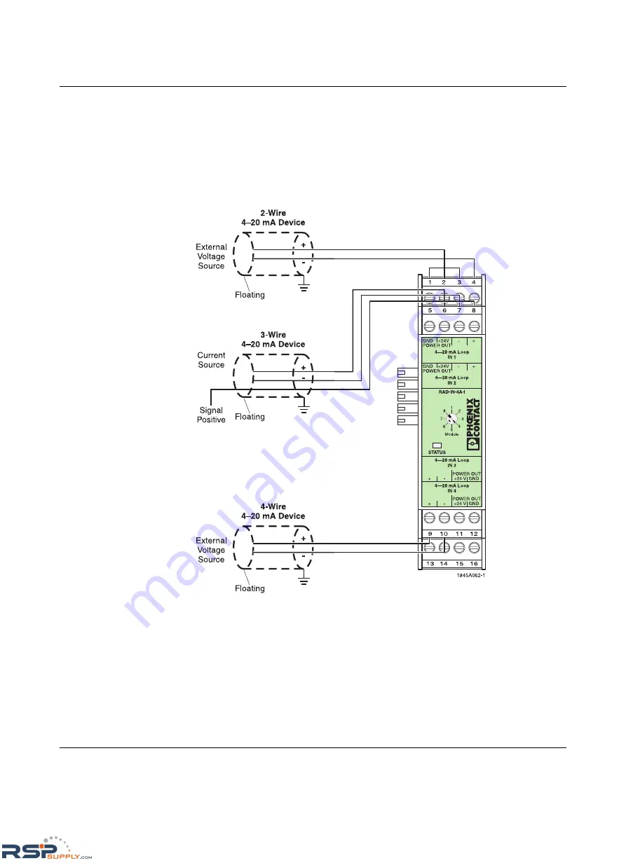
If using the Analog Input Module, use the wiring diagram shown in Figure 5-5.
Figure 5-5
RAD-IN-4A-I Analog Input Module wire diagram
RSPSupply - 1-888-532-2706 - www.RSPSupply.com
http://www.RSPSupply.com/p-12970-Phoenix-Contact-2900016-Radio-900-MHz-Ethernet-Radio.aspx


