Bus Configuration for I/O Modules (RAD-ISM-900-EN-BD-BUS only)
2476_en_I
PHOENIX CONTACT
5-5
5.1.4
Configuring Radios Connected to I/O
PLC Interface Configuration
To enable communication between the RAD I/O and a Modbus-based master, the Modbus
address and Communications Timeout must be set, and a communications stream must be
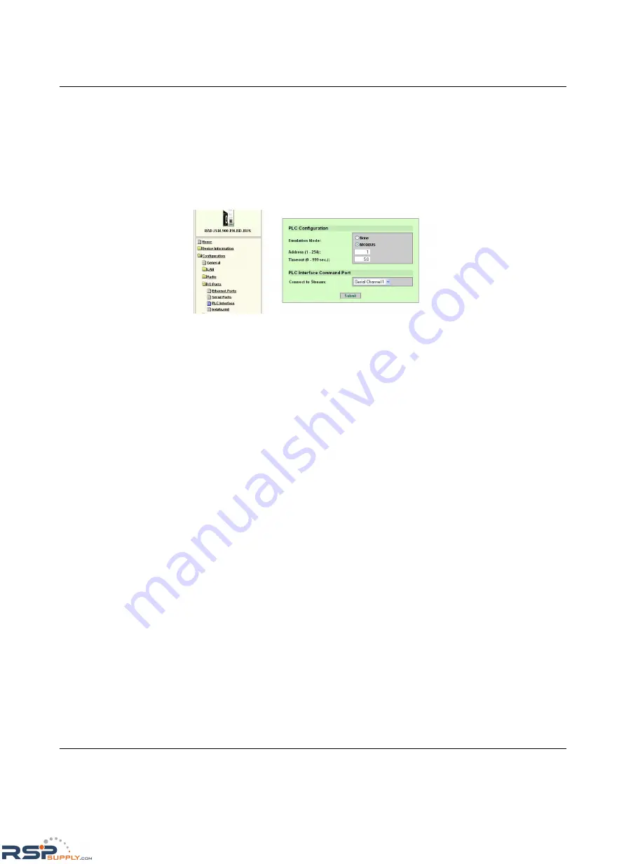
assigned. These parameters are found on the PLC Interface Configuration web page.
Configure the radio as described in the following steps so the I/O modules can be accessed.
1.
Click “Configuration… I/O Ports… PLC Interface” on the left-hand menu.
Figure 5-1
“PLC Configuration” menu
2.
Set
PLC Emulation Mode.
To enable communications between the RAD I/O and a Modbus-based master, the
PLC Emulation mode must be set to
MODBUS
.
3.
Enter the
PLC Address
.
Enter the Modbus node address that you wish to assign to the radio. The address
should be between 0 and 254 and must be different from all other Modbus devices in
the network. A wrong address setting will result in the PLC address box resetting to 0.
4.
Enter a
Timeout
value.
The timeout setting controls a communications watchdog timer that triggers the I/O fault
mode in the event communications between the PLC/Modbus master and the I/O are
disrupted. The timeout default setting is 5 seconds. Enter a value between 0 and
999 seconds. A “0” setting disables the communications watchdog timer. For more
detailed information, see “Timeout Setting for I/O Control” on page 5-5.
5.
Enter the value to
Connect to a Stream
.
One of the two serial or local communication streams must be dedicated to handle the
communication to and from the I/O. Select either of the two serial or local channels.
Since only one stream can control all the I/O in the system, the channel selected must
be the same for the Modbus master, and all I/O connected to all radios.
Timeout Setting for I/O Control
A communications timeout setting is needed because there can be many intermediate radio
or Ethernet segments between the Modbus (RTU or TCP) master device and the various
slave radio’s I/O. Due to the multiple intermediate segments, communications can be
stopped even though the radio link or Ethernet link to the radio is intact. The timeout function
compares the elapsed time between the last Modbus read or write commands, and a preset
value. If the actual time exceeds the timeout preset, the radio assumes that the I/O modules
are no longer under control, and sets all the I/O attached to the radio to their fault state. The
value should be set to the slowest machine or process function that the I/O (attached to the
radio) is controlling.
It is important to note that the I/O will not fail to its fault off condition in the event of an RF link
loss. The I/O will only fail to the fault off condition when the timeout setting value is reached.
Enter a value of “0” will disable the watchdog, and the fault condition will also be disabled.
RSPSupply - 1-888-532-2706 - www.RSPSupply.com
http://www.RSPSupply.com/p-12970-Phoenix-Contact-2900016-Radio-900-MHz-Ethernet-Radio.aspx


