
Hardware Repair
MCP9350i
12.
EN 45
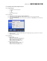
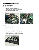
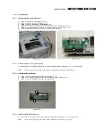
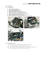
12.7.3. TV Daughterboard Subassembly Removal
1.
Remove the top cover. See paragraph 12.1.1.
2.
Remove the riser card subassembly. See paragraph 12.5.1.
3.
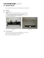
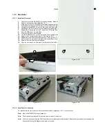
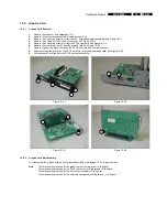
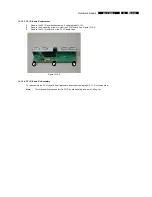
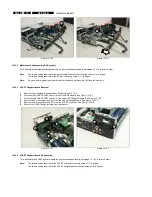
Remove the thermistor (4) from the motherboard. See Figure 12.7-4.
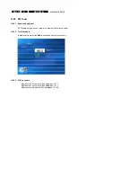
4.
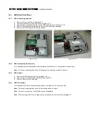
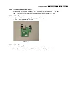
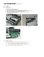
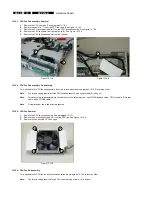
Remove the 2 mounting screws (5) from the TV daughterboard subassembly. See Figure 12.7-5.
5.
Remove the TV daughterboard subassembly from the chassis.
Figure 12.7-4
Figure 12.7-5
12.7.4. TV Daughterboard Subassembly Re-Assembly
To re-assemble the TV daughterboard subassembly, do all processes described in paragraph 12.7.3 in reverse order.
Note:
The torque setting required for the TV daughterboard subassembly mounting screws (5) is 8kg-cm
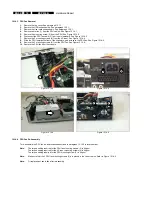
12.7.5. TV
Daughterboard
Removal
1.
Remove the top cover. See paragraph 12.1.1.
2.
Remove the riser card subassembly. See paragraph 12.5.1.
3.
Remove the TV daughterboard subassembly. See paragraph 12.7.3.
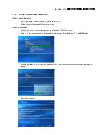
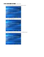
4.
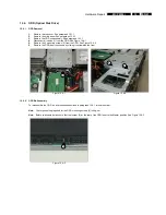
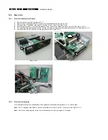
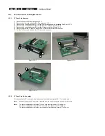
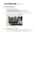
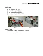
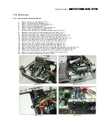
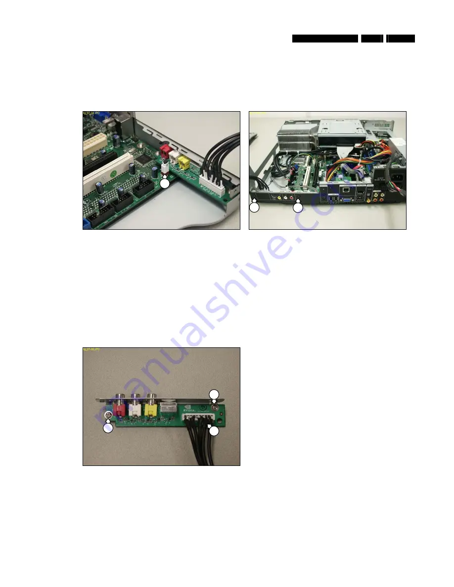
Disconnect the TV daughterboard cable (6). See Figure 12.7-6.
5.
Remove the 2 mounting screws (7) from the TV daughterboard. See Figure 12.7-6.
6.
Remove the TV daughterboard from the TV daughterboard cage.
Figure 12.7-6
12.7.6. TV
Daughterboard
Re-Assembly
To re-assemble the TV daughterboard, do all processes described in paragraph 12.7.5 in reverse order.
Note:
The torque setting required for the TV daughterboard mounting screws (7) is 6kg-cm
4
5
5
7
6
7


