EN 40
12.
MCP9350i
Hardware Repair
12.3. HDD (Hard Disk Drive)
12.3.1. HDD Subassembly Removal
1.
Remove the top cover. See paragraph 12.1.1.
2.
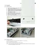
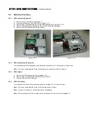
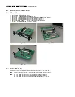
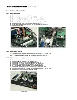
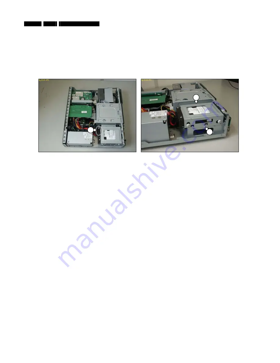
Disconnect all cables (1) from the HDD. See Figure 12.3-1.
3.
Remove the 2 mounting screws (2) from the HDD subassembly. See Figure 12.3-2.
4.
Slide the HDD subassembly towards the left, until the locking tabs disengage.
5.
Remove the HDD subassembly from the chassis.
Figure 12.3-1
Figure 12.3-2
12.3.2. HDD Subassembly Re-Assembly
To re-assemble the HDD subassembly, do all processes described in 12.3.1 paragraph in reverse order.
Note:
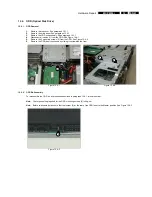
The torque setting required for the HDD subassembly mounting screws (2) is 8kg-cm
12.3.3. HDD
Removal
1.
Remove the HDD subassembly. See paragraph 12.3.1.
2.
Remove the 4 mounting screws and bushes from the HDD.
3.
Slide the HDD out of the HDD cage.
12.3.4. HDD
Re-Assembly
To re-assemble the HDD, do all processes described in paragraph 12.3.4 in reverse order.
Note:
The torque setting required for the HDD mounting screws is 4kg-cm
Note:
There are no jumpers on the HDD that require configuration.
Note:
When replacing a HDD a disc image must be installed on the new drive. See paragraph 13.
1
2
2

