Hardware Repair
MCP9350i
12.
EN 43
12.6. Graphic
Card
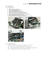
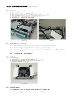
12.6.1. Graphic Card Removal
1.
Remove the top cover. See paragraph 12.1.1.
2.
Remove the riser card subassembly. See paragraph 12.5.1.
3.
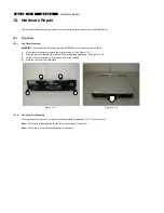
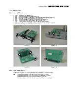
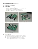
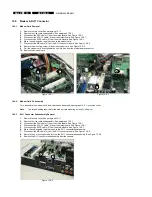
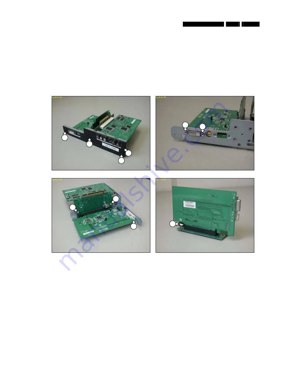
Remove the 4 mounting screws (1) from the riser card subassembly backplate. See Figure 12.6-1.
4.
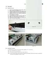
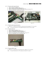
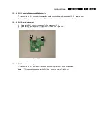
Remove the 2 screws (2) from the DVI connector. See Figure 12.6-2.
5.
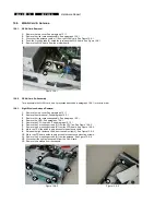
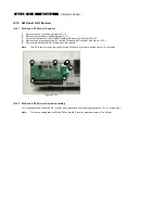
Remove the 2 mounting screws (3) from the PCI-E riser card. See Figure 12.6-3.
6.
Remove the mounting screw (4) from the graphic card. See Figure 12.6-3.
7.
Remove together the graphic card and the PCI-E riser card from the riser bracket.
8.
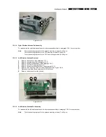
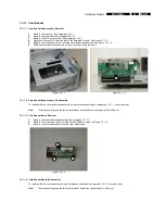
Push the locking tab arm (5) on the PCI-E connector to release the graphic card. See Figure 12.6-4.
9.
Pull the graphic card free from the PCI-E riser card connector.
Figure 12.6-1
Figure 12.6-2
Figure 12.6-3
Figure 12.6-4
12.6.2. Graphic Card Re-Assembly
To re-assemble the graphic card, do all processes described in paragraph 12.6.1 in reverse order.
Note:
The torque setting required for the graphic card mounting screw (4) is 6kg-cm
The torque setting required for the PCI-E riser card mounting screws (3) is 6kg-cm
The torque setting required for the DVI connector screws (2) is 6kg-cm
The torque setting required for the riser card backplate mounting screws (1) is 8kg-cm
2
1
5
3
3
1
1
1
2
4

