4 Testing and Maintenance
Performance Assurance Tests - Checking and Calibrating the Gas Analyzer
56
Annual Checks
Perform the following procedure once a year
1
Connect a PC/Laptop running the Service Software (VISIA tool) to the instrument and wait for
the first zero calibration after the start up period. (Make sure that zero mode is switched to
Auto
-
see “Zero Calibration” on page 59)
2
Check that there are no reported errors.
3
Perform the pneumatic tests:
a. Leak check
b. Flow rate check
c. Pressure sensor test.
4
Gas calibration tests
Connecting the Gas Analyzer to a PC/Laptop
To set up a computer as a service host for the gas analyzer, a serial connection must be established with
the IntelliVue G1/G5 PC cable (for part number see "Equipment Required for Checking"). Connect
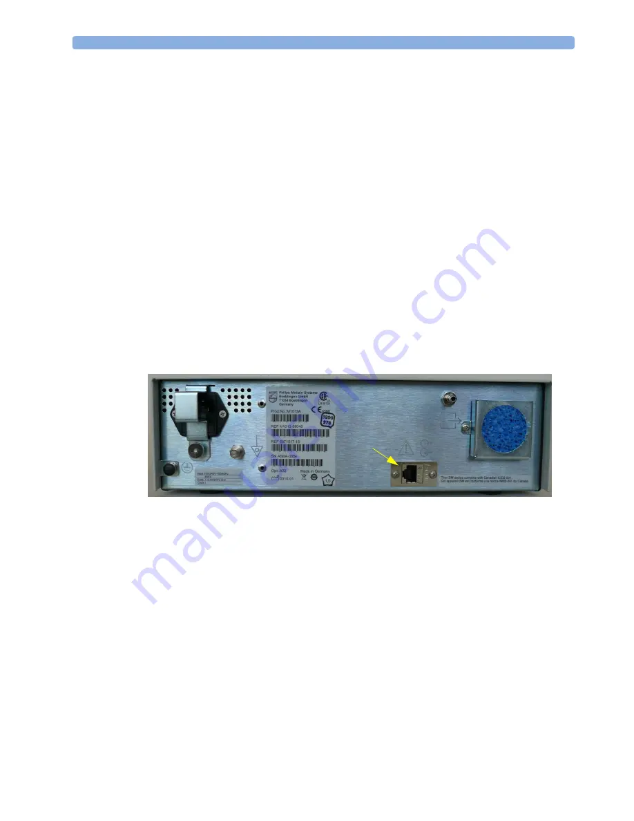
the RJ45 connector of the cable to the appropriate receptacle on the back of the gas analyzer (see Figure
6), and then connect the D-SUB9 connector of the cable to the serial port of your computer.
Switch on the gas analyzer and then start the VISIA software on your computer.
Figure 6 RJ45 connection on the back of the gas analyzer
Getting started with the VISIA software
N O T E
After each use of the VISIA tool, the G1/G5 must be switched off and back on again before being used
for patient monitoring.
When the VISIA tool starts up, it is switched to
Standby,
Breath Detection is
Enabled
, and the Pump
Flow Level is
Off
. Check the COM port for correct settings (Baud Rate: 19200) and push the
“Connect” button if the connection was not established automatically after starting the VISIA tool.
In order to keep the gas analyzer running, always do the following first:
1
Switch the tool to
Operate
,
2
Switch Breath Detection to
Disabled
(as shown in Figure 7) and
RJ45 serial
communication
interface


