


Red
Yellow
Magenta
Green
/t
`
B
l
u
e
Cyan
III.
SD 3906
Osc. out of lock.
Osc. out of lock.
(C)
Red
_ a g e n t s
Point N
Yellow
0 k B l u e
G
r
e
e
Cyan
Osc. in lock.
(0)
Osc. in lock.
Pins 4 and 5 of D7018 shorted.
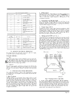
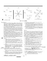
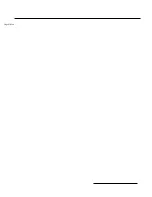
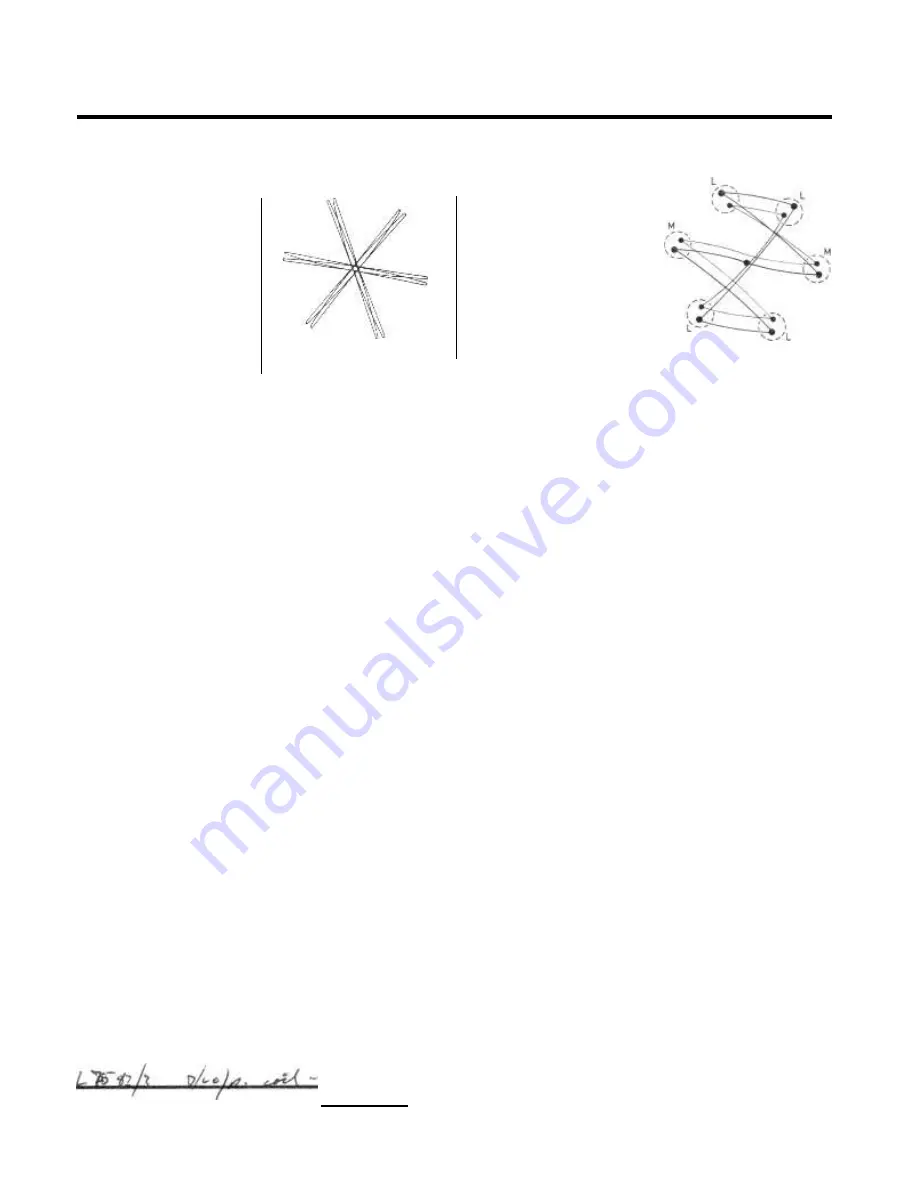
Fig. 17. X - Y displays
Decoder alignment
One of the most accurate means of aligning a PAL de-luxe decoder
involves the use of an X-Y oscilloscope. This can be either a special
instrument such as the Philips GM5639, or an ordinary oscilloscope
(bandwidth > 200kHz) which provides access to its X plates
(Philips PM3230). The R-Y output from the demodulator is coupled
to the Y plates of the 'scope (vertical deflection) and the B-Y output
to the X plates (horizontal deflection).
Since the deflection axes of the oscilloscope coincide with the R-Y
and B-Y axes, using a standard colour bar pattern and the receiver
operated with its reference oscillator in lock, a vector display will
be obtained (see Fig. 17C) each large dot representing the phase
and amplitude of an individual signal component. Alternatively,
the oscillator can be adjusted to be out of lock, and the dots then
become thin ellipses as shown in Fig. 17A, once again
employing a standard colour bar pattern.
Two methods are described to align the decoder, the first one using
the standard colour bar signal as provided by the B.B.C., or the
Philips PM5506 pattern generator in conjunction with an X-Y
oscilloscope. The second method uses the PM5506 generator only.
The adjustments are made using the pattern produced on the screen
as an indicator, thus avoiding the need for an oscilloscope.
Note. Before proceeding with the decoder alignment, it is essential
that the A.P.C. loop is correctly adjusted and that the I.F. and chro-
ma. bandpass circuits are correctly aligned.
Method A
1.
Apply the standard colour bar signal to the receiver aerial
socket and set up the controls for a normal picture.
2.
Apply -5 to -10v. from the resistor network (see Fig. 16) to
pin 2 of V7003 in order to control the gain of the chroma
amplifier in the absence of chroma. A.G.C.
3.
Apply -10v. from the resistor network to the slider of R7618
in order to tune the reference oscillator out of lock (tag 1 on
can F).
4 Connect pin 3 of V7007 (13
:
Loutp_ut) to the X plates of the
oscilloscope (or pin 9 ofi'Nt no X amplifier is available)
and pin 3 of V7005 (R-Y out
to the Y input. Adjust oscil-
loscope gain controls
am flip largest possible undistorted
display, and the potentiometer NE in Fig. 16 to achieve near
R
-
e G7
stationary ellipses.
AP-
•
4 T
1
-
1
5. Adjusta so that all the ellipses become as thin as possible,
4
9
55/1ffificuliffy the ellipse on the 'nearly vertical' axis (see Fig.
17A).
Adjust"1._so that all the tips of the duplicated ellipses
o 17B shows these ellipses before the adjustment is
carried out.
7. Adjust L7562/3 so that the diagonal ellipses, especially on the
magenta/green axis become as thin as possible. It may not be
possible to make all the ellipses into thin lines with L7562/3,
in which case the best compromise should be achieved.
--
8.
Synchronise the reference oscillator by removing the -1.0v.
source from the slider of R7618.
9.
Adjust L7561 and L7559/60 for maximum amplitude of the
stationary vector dot pattern display (see Fig. 17C) at the same
time checking that the half amplitude dots, in particular those
on the blue axis at point N, coincide (these dots may appear
rather fainter on the oscilloscope).
10.
Short-circuit pins 4 and 5 of the delay line D7018 and adjust
L7521/2 for equal spacing of dots L in Fig. 17D, then adjust
L7526/7 for equal spacing of dots M in Fig. l7D. Remove the
short-circuit from the delay line.
Method B
Note. Adjustment of the chroma. coupling coils L7521/2 and
L7526/7 should only be carried out if the coils have been replaced
or are known to be misadjusted. If these coils have to be adjusted,
then it will also be necessary to adjust the chroma. demodulators
(L7559-63). Consequently the procedure set out below gives the
complete sequence of adjustment to cover this condition. In the
event of the chroma. demodulators only being out of adjustment,
then operations 1 to 7 should be ignored.
I. Disconnect the I.F. lead between the tuner and the I.F. panel.
2.
Connect a 1.51(1) resistor and 1KpF capacitor in series between
tags 1 and 7 of the demodulator unit (can "C").
3.
Unscrew the cores of L7521/2 and L7526/7 level with the tops
of the coil cans.
4.
Connect a high resistance D.C. voltmeter between tag 5 of can
"C" and chassis (+ ve to chassis).
5.
Screw in the core of L7521/2 until the reading just starts to
increase (about 0.2 volts).
6.
Remove the R.C. coupling from tag 7 and reconnect to tag 6.
Transfer the meter connection from tag 5 to tag 3.
7.
Screw in the core of L7526/7 until the meter reading just
shows a change (about 0.2 volts).
8.
Connect the R.F. output of the pattern generator PM5506
to the receiver aerial socket and adjust the controls to display
improvement
(A)
IB
)
4
y
9
,
•
the "cross hatch" with sharp clearly defined vertical lines.
9.
Switch the generator to "Delay" and adjust 561 for the-same-
1 --
Z I;
L
7
colour in bars 3
and 4 (keethe setting of the colour control
fairly low). p _
i
i •
-p
e..•thv
uz
p
10.
Adjust L75i or minimum "venetian blinds" in bar 2.
11.
Switch the generator to "Phase" and adjust the colour control
for a fairly low level of saturation.
13.
Adjust
lower
15.
Adju
low
17.
Re
resi
f
ts
9/60 to obtain the same colour in the upper and
rt of bars 1 and 2 (ignoring bar 3).
L75 /3 to obtain the same colour in the upper and
part f bar 3 (ignoring bars 1 and 2).
t op ations 2, 6 and 7 until no further
Содержание G22K511
Страница 3: ...G22K511 G25K512 Page Two ...
Страница 12: ...Page Ten ...
Страница 14: ...Page Eleven ...
Страница 19: ...Page Fifteen ...


