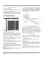
4.
Alignment of the inter-carrier sound I.F.
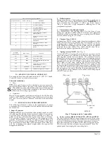
Apply the sweep generator to
TPI
via the terminating pad (see
Fig. 9) and the oscilloscope to TP3. Set R2073 to its mid position,
then trim L2526, L2504, L2503, L2643/4 and L2645 for maximum
height and symmetry centred on 6.0MHz. Reconnect the oscillo-
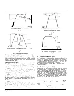
scope to TP4 and trim L2628/9 for a symmetrical 'S' curve of
maximum amplitude. Finally reset R2073 (see para. 5 below).
5.
Adjustment of ratio detector balance control R2073
Apply a 6.0MHz amplitude modulated signal to TP1 and connect
the oscilloscope to TP4. Adjust R2073 for minimum output.
6.
Setting of L2573/4 neutralising coils
The adjustment of L2573/4 is preset during manufacture and should
not be disturbed during alignment. However, in the event of
accidental movement of the core, the adjustment may be made as
follows:-
Set the core flush with the top of the coil can, then screw the core
in 5 turns and seal with soft wax.
7.
Chroma. bandpass alignment
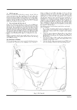
Short-circuit pins 4 and 5 of V7008 and connect the anode of X7326
to chassis. Connect a 6v. battery from pin 2 of V7003 to chassis
(positive terminal to chassis). Open-circuit solder link
B
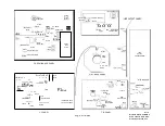
(see
Fig.
33) and apply the sweep generator to TP2 via the terminating pad.
Connect the oscilloscope to TP6 via the detector unit shown in
Fig. 11. Trim L2773 for minimum response at 6.0MHz. Trim
L7517/8, L7508/9, L7506 and L2775 for maximum response with
correct curve shape and bandwidth centred on 4.43MHz (see
Fig. 13). Finally, resolder link
B
on the print, remove the bias
battery and short circuits from X7326 and pins 4 and 5 of V7008
then check the adjustment of R7179 and R7206 (see section H,
paras, 22 and 23).
Note.
When alignment of the chroma. bandpass
circuit has been
completed, the decoder alignment must be checked, particularly
the setting of L7559/60 and L7561.
I.F. ALIGNMENT TABLE
Input from
C20.4I
sweep generator to
and turn R2092 fully
clockwise.
TP7 (tuner injection point) via the
terminating
pad (see Fig. 9). Connect
a short-circuit across
Circuit
Marker
frequency
Damp
to chassis
Trim
Trim for
Oscilloscope
connection to
I.
Tuner I.F.
36.0MHz
-
L3404
Max.
TP5 via damper/
detector (Fig. 10)
2.
Ch. I rej.
-
-
L2586
Unscrew core
level with
top of can
-
3.
Sound ledge
atten.
33.5MHz
-
L2555
Min.
TP5 via damper/
detector (Fig. 10)
4.
I st vis. I.F.
37.0MHz
-
L2554
Max.
,,
5.
2nd vis. I.F.
37.0MHz
-
L2564
Max.
„
6.
Ch. I rej.
41.IMHz
-
L2783
Min.
„
7
.
„
41.5MHz
L2783
(point A
Fig. 33)
L2586
Min.
„
8.
1st vis. I.F.
39.0MHz
-
L2554
Max.
„
9.
2nd vis. I.F.
37.0MHz
-
L2572
Max.
„
10.
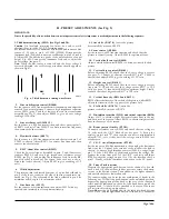
Check response curve
shape.
against Fig. 15 and, if necessary, readjust L2572, L2554 L2564 and L3404 to obtain the correct curve
11.
Sound ledge
filter
33.7MHz
-
L2603
Min.
TPI
12.
3rd vis. I.F.
37.0MHz
TP5
L2598
Max.
71
13.
,,
37.0MHz
-
L2596
Max.
,,
14.
Luminance
detector
37.5MHz
-
L2620
Max.
t,
15.
„
37.5MHz
-
L2621
Max.
„
16.
Check response curve
shape and limits.
against Fig. 12 and, if necessary, readjust L2598, L2596, L2620 and L262I to obtain the correct curve
17.
Chrominance
detector
35.IMHz
-
L2744
Curve
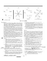
Fig. 14
TP2
18.
„
39.5MHz
-
L2745
, ,
9 t
19.
"
37.2MHz
-
L2746
Min.
20.
„
37.9MHz
-
L2747
Min.
,P
21.
Check response curve against Fig. 14 and, if necessary, readjust L2744-47 to obtain correct curve shape and limits.
22.
With C2041 short-circuited and no signal input, connect a voltmeter across R2086 and adjust R2092 for a reading of 2.4 volts.
Page Thirteen
Содержание G22K511
Страница 3: ...G22K511 G25K512 Page Two ...
Страница 12: ...Page Ten ...
Страница 14: ...Page Eleven ...
Страница 19: ...Page Fifteen ...

