


C
—
RECEIVER NOTES
1.
Mains supply voltage
This colour receiver has been designed to be used with a nominal
mains voltage of 240v. a.c. Engineers are advised that operating a
receiver on a mains supply which provides poor voltage regulation
(i.e., an isolation transformer rated at less than 500 watts) may
present difficulties in obtaining optimum convergence.
Note.
—
Once the receiver controls have been set-up, slight re-adjust-
ment may be necessary if the set is operated from a supply voltage
different from the initial setting-up voltage.
2. X-ray radiation warning
The voltages and currents on the cathode ray tube are higher in a
colour receiver than in a monochrome type, and as a result, the
X-rays produced will have a greater penetrating power and will
be present in larger quantities. In practice, this means that suitable
protection has to be built into a receiver in order to reduce the radia-
tion hazard to an acceptable level. It is important that personnel
involved in installation and servicing should be well aware of any
possible dangers.
The radiation problems are confined to X-rays generated by two
sou rce s:
(a)
The cathode ray tube
(b)
The extra high tension generator
During the development of the `G6' colour television chassis,
special attention has been given to these points. With the backplate
removed no significant radiation is present, and therefore the maxi-
mum dose rate is much less than the accepted danger level. This low
level of radiation is due to :
—
(i)
The absorbing power of the glass in the cathode ray tube.
(ii)
The C.R.T. metal cone shield provided for magnetic screening.
(iii)
The metal screening enclosing the E.H.T. generator (L.O.P.T.
assembly).
Provision is made on the E.H.T. generator so that the unit is in-
operative when the side cover of the screening can is removed. This
takes the form of an inter-lock switch disconnecting the H.T.
supply. On no account must this inter-lock be tampered with.
Line stabilisation control (R5040)
It is most important that this control is adjusted to the correct boost
voltage setting (see Adjustments). Any increase above this setting
will cause the E.H.T. voltage to rise, resulting in possible forward
X-ray radiation from the C.R.T. face.
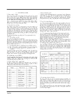
3. Colour coding of H.T. supply leads
In order to assist service engineers in identifying the various H.T.
supply leads to different parts of the receiver, a system of colour
coding these leads is used which is shown below.
Supply
Lead colour
Voltage
H.T.2
Red
+285v.
H.T.2 (fused)
Red/Brown
+285v.
H.T.3
Red/Orange
+250v.
H.T.4
Red/Yellow
+230v.
H.T.5
Red/Green
+220v.
H.T.6
Red/Blue
+220v.
H.T.7
Red/Grey
—
120v. stab.
H.T.8
Black/Orange
+12v. stab.
H.T.9
Black/White
+18v.
4. Special trimming tool
A special star-shaped trimming tool is necessary for the alignment
of the tuner I.F. coil, and also for adjustment of certain other
cores. This trimming tool is available as part of the Philips
trimming tool kit 800/TX, and engineers are advised that any attempt
to adjust these cores with a non-standard tool may damage them.
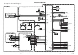
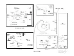
5. Use of the circuit diagram
(a)
The complete circuit of the `G6' single-standard colour tele-
vision receiver (less integrated tuner) has been drawn out on two
separate sheets accompanying this manual. The connecting leads
have been so arranged that the two halves of the circuit may be
permanently joined together with transparent adhesive tape if
required. H.T. points from the power supply circuits are shown
set in boxes, and an equivalent symbol is indicated at the particular
part of the circuit to which it is connected (see also note in colour
coding of H.T. leads
—
para. 3 above).
(b)
For component identification on the circuit, a grid refe
system is used. This has been arranged so that each sheet may
be
used either separately or joined together, the letters at the top of the
circuit running from A to S and the numbers at the side of each
diagram running down from 1 to 7. The grid location for all com-
ponents has been included in the Spare Parts List.
Where it has been found impracticable to show direct connections
between various parts of the circuit, e.g. the line pulse feeds
from L5505 and L5524, a grid reference has been included to assist
in locating the appropriate circuit connections.
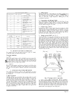
(c)
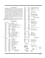
In order to identify a particular component on the circuit
with its position in the receiver, a coding system for component
numbers is used. For instance, any component with a 2000 number
is located on the I.F. panel, and a component with a 5000 number
will be found in the line transformer assembly. The complete
coding system is as follows:
L O C A T I O N
Number
Valves &
Semicon.
Resistors
Capacitors
Coils
Main chassis and sub.
assemblies
1100
1000-1100
1000-1100
1500
C.R.T. base panel
1700
1000
1000
1500
Convergence unit
1200-1300
1200-1300
1200-1300
1600
Deflection, converg-
ence and degaussing
yokes
—
1700
1700
1700
I.F. Panel
2000
2000
2000
2000
Integrated tuner
3000
3000
3000
3000
Time Base
4000
4000
4000
4000
Line transformer
assembly
5000
5000
5000
5000
Chroma. panel
7000
7000
7000
7000
6. Connecting plugs and sockets
The plugs and sockets used for interconnecting assemblies are
colour coded to enable service engineers to identify where each is
fitted to the main chassis. This takes the form of a coloured ring
around the plug on the appropriate connection panel, and a
similarly coloured sleeve marker around the leads into the respec-
tive socket.
Note.
—
Sockets should never be removed from the plugs by pulling
on the leads, since this practice may lead to the pins within the
sockets being damaged.
Page Four
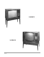
Содержание G22K511
Страница 3: ...G22K511 G25K512 Page Two ...
Страница 12: ...Page Ten ...
Страница 14: ...Page Eleven ...
Страница 19: ...Page Fifteen ...