19.
Release of tuner push-buttons
In the event that all four push-buttons have been accidentally
pressed in simultaneously, they may be released by pressing in the
second button from the left (BBC2) still further.
20.
A.M. rejection (R2073)
Tune in the receiver and adjust R2073 for minimum buzz on
sound.
21.
Preset A.G.C. (R2092)
Connect a voltmeter across R2086 and short-circuit C2041. Then,
with no signal input, adjust R2092 to obtain a reading of 2.4
volts.
22.
Chroma. A.G.C. adjustment (R7179)
Adjust the receiver to give a normal colour picture, then turn the
colour control to maximum. Set R7179 to give slightly more than
correct saturation. Detune the receiver slightly to check that the
colour killer circuit operates before luminance is lost. (If not,
make a slight readjustment to R7179),
23.
Chroma. tracking adjustment
(R7206)
The correct setting for R7206 should ensure that as the contrast
control is varied, the saturation will remain in step. Adjust R7206
until it is found that both luminance and saturation levels track
together over the range of contrast settings.
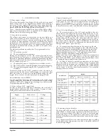
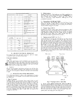
In the event of transistor or valve replacement, the following pre-
set control adjustments must be checked and re-adjusted if neces-
sary.
Transistor/valve
Control
T2142
R2092
T7012
R7173
T7015
L7634
V1706, V2001
R7285, R1279, R1280,
R1281, R1077, R1080
V4001
L4501/2, R4071, R5040,
R5053
V4002, V4004
R4098, R4105, R4101,
R4115, R4121, R4120
V5001,
V5004,
V5002,
V5005
V5003,
R5040, R5053, R5045,
R7301
V7001, V7002, V7003
R7179, R7206
V7005, V7006, V7007
R7173, R7245, R7236
V7008
L7624-6, R7168
V7009
L7651/2, L7638
I
—
CONVERGENCE
General
Before attempting any adjustments of convergence, the receiver
must be allowed to warm up for at least 20 minutes, and all
normal adjustments of height, width, linearity and raster
correction must be completed.
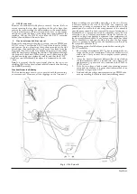
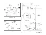
Note: In the following notes on purity, static and dynamic conver-
gence, the numbering of the controls relates to Fig. 8. The diagram
attached to the convergence panel may be employed in conjunction
with these instructions, using the waveforms to help explain the
function of each control.
Degaussing
The receiver is fitted with an automatic degaussing circuit which
operates each time the set is switched on from cold. However, in
cases where the C.R.T. and/or associated metal parts
have been
subjected to extra strong magnetic fields, it may be necessary to pass
an external degaussing coil across the C.R.T face and
in each
corner before purity/convergence adjustments are carried out.
At no time whilst using an external degaussing coil
should it be al-
lowed
to come closer to the face of the C.R.T. than is necessary for
complete degaussing, otherwise permanent damage may
be caused to
the shadow-mask plate inside the tube.
Notes:
1.
When readjusting the purity ring magnets, care should be
taken that no undue force is exerted on the rings which may con-
sequently damage the plastic retaining clips.
2.
In common with normal servicing practice, the receiver should
not be switched off and on again in rapid succession when warmed-
up. This may not only adversely affect valve heaters, etc., but it is
possible that static convergence errors may occur.
3.
All purity, convergence and grey scale adjustments should be
carried out under subdued lighting conditions.
Purity
1.
Switch off the green and blue guns (depress switches 17 and 18)
and remove the receiver signal input (pull out the tuner output lead
on the I.F. panel). Purity should be adjusted on a plain red raster,
using only average brightness.
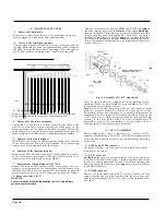
2.
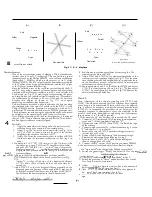
Cancel the purity ring magnets by setting the notch A in each
ring in line with the other (see Fig. 7).
3.
Loosen the wing nuts B (see Fig. 7) and push the deflection
coils fully forward. The red area should now be moved to the
centre of the screen by adjusting the purity magnets.
4.
Move the deflection coils backwards until the red area fills the
whole screen. Small errors may be overcome by a further slight
adjustment of the purity magnets.
5.
Switch off the red gun (19) and switch on the green gun (18).
Check that the whole of the screen is green.
6.
Switch off the green gun (18) and switch on the blue gun (17).
Check that the whole of the screen is blue. Finally, tighten the wing
nuts B.
Spot
Deflection Coils
Blue Shift
A
Green Shift
Convergence
Assembly
7 :
0 a
SD3295
Blue Lateral
Shift Magnet
Fig. 7. Deflection assembly
Red Shift
Purdy Magnets
Содержание G22K511
Страница 3: ...G22K511 G25K512 Page Two ...
Страница 12: ...Page Ten ...
Страница 14: ...Page Eleven ...
Страница 19: ...Page Fifteen ...


