Service Modes, Error Codes, and Fault Finding
EN 34
F21RE AB
5.
7.
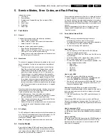
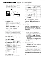
Plug the mains adapter in an mains outlet and switch on the
ComPair interface. The green and red LEDs light up
together. The red LED turns off after approximately 1
second, while the green LED remains lit.
8.
Start the ComPair program and read the "introduction"
chapter.
Figure 5-2 ComPair set-up
5.4.4
How to Order
ComPair order codes (EU/AP):
•
Starter kit ComPair32/SearchMan32 software and
ComPair interface (excl. transformer): 3122 785 90450.
•
ComPair interface (excluding transformer): 4822 727
21631.
•
Starter kit ComPair32 software (registration version): 3122
785 60040.
•
Starter kit SearchMan32 software: 3122 785 60050.
•
ComPair32 CD (update): 3122 785 60070.
•
SearchMan32 CD (update): 3122 785 60080.
•
ComPair interface cable: 3122 785 90004.
5.4.5
Stepwise Start-up / Shut-down
Under normal circumstances, a fault in the power supply, or an
error during start-up, will switch the television to protection
mode. ComPair can take over the initialisation of the television.
In this way, it is possible to distinguish which part of the start-
up routine (hence which circuitry) is causing the problem.
Stepwise start-up explanation
This is realised via ComPair and is very helpful when a
protection is activated (see also paragraph "Protections").
Table 5-1 Stepwise Start-Up Table
Stepwise shutdown explanation
In the stepwise shutdown mode, state 2 and 4 are skipped.
Table 5-2 Stepwise Shut-Down Table
Note (*): When the set is in stepwise mode and, due to
stepping-up, a protection is activated; the set will really go into
protection (blinking LED). The set will not leave the stepwise-
mode however. By stepping down, the set can be activated
again, until state X where the protection was activated. At state
(X-1) diagnostic measurements can be performed.
5.5
Error Codes
The error code buffer contains all detected errors since the last
time the buffer was erased. The buffer is written from left to
right. When an error occurs that is not yet in the error code
buffer, it is written at the left side and all other errors shift one
position to the right.
5.5.1
How to Read the Error Buffer
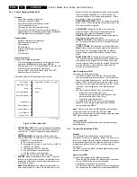
It is possible to read out the error buffer in three ways:
•
On the screen while in Service Alignment Mode (SAM). If
there is a picture, this is the easiest way to read the error
buffer. In the SAM main menu, the last 10 error codes,
which have occurred, are displayed. The most recently
detected error code is displayed on the left side. Examples:
–
003 000 000 000 000: error code 3 is the last and only
detected error.
–
002 003 000 000 000: error code 3 was detected first
and error code 2 is the last detected (newest) error.
•
With the CODE 1 and CODE 2 lines in CSM.
•
With ComPair.
5.5.2
How to Clear the Error Buffer
It is possible to clear the error buffer in two ways:
•
By selecting the item "reset Error Buffer" in the SAM main
menu.
•
By pressing the following key sequence on the remote
control transmitter: MUTE - 062599 - OK.
Note: When the error buffer is full (10 codes), no new errors
can be stored. The set monitors how long every error is stored
in the error buffer. If a false error is in the buffer, it will be
deleted after 50 hours. If an actual error is in the error buffer, it
will be written to the buffer again after 50 hours. This is a
safeguard to ensure that the history of the error codes is stored.
To help ensure that you are not reading false error codes, you
may want to record the contents of the error buffer, reset the
buffer, and see which error codes are generated again by the
set.
State Mode description
Display
LEDs(*)
Enabled
protections
0
- Low power standby
- uP in Standby.
Red 'on'
None
1
- High power standby.
- TV-set in standby.
RedFlash
1 time
None
2
- Supply 'on'.
- Protections 5V2 and
8V6 activated.
Orange/
GreenFlash
2 times
67 and 68
3
- Sound ICs initialised.
- Protections FBX and
TUNER activated.
Orange/
GreenFlash
3 times
Plus 77 and 80
4
Not used in FTV
5
- TV operates.
- Unblanked picture.
Orange/
GreenFlash
5 times
86532027_003.EPS
050898
PC
VCR
I
2
C
Power
9V DC
State Mode description
Display
LEDs(*)
Disabled
protections
5
- TV operates.
- Unblanked picture.
Orange/
GreenFlash
5 times
-
4
- All protections are
'on'.
Orange/
GreenFlash
4 times
-
3
- Sound ICs initialised.
- All protections 'off'.
Orange/
GreenFlash
3 times
-
1
- High power standby.
- TV-set in standby.
Red 0.5 Hz-
Flash
1 time
80, 77, 68, and
67
0
- Low power standby.
- uP in Standby.
Red 'on'
-
Содержание F21RE
Страница 7: ...Directions for Use EN 7 F21RE AB 3 3 Directions for Use ...
Страница 8: ...Directions for Use EN 8 F21RE AB 3 ...
Страница 9: ...Directions for Use EN 9 F21RE AB 3 ...
Страница 10: ...Directions for Use EN 10 F21RE AB 3 ...
Страница 11: ...Directions for Use EN 11 F21RE AB 3 ...
Страница 12: ...Directions for Use EN 12 F21RE AB 3 ...
Страница 13: ...Directions for Use EN 13 F21RE AB 3 ...
Страница 14: ...Directions for Use EN 14 F21RE AB 3 ...
Страница 15: ...Directions for Use EN 15 F21RE AB 3 ...
Страница 16: ...Directions for Use EN 16 F21RE AB 3 ...
Страница 17: ...Directions for Use EN 17 F21RE AB 3 ...
Страница 18: ...Directions for Use EN 18 F21RE AB 3 ...
Страница 19: ...Directions for Use EN 19 F21RE AB 3 ...
Страница 20: ...Directions for Use EN 20 F21RE AB 3 ...
Страница 21: ...Directions for Use EN 21 F21RE AB 3 ...
Страница 22: ...Directions for Use EN 22 F21RE AB 3 ...
Страница 23: ...Directions for Use EN 23 F21RE AB 3 ...
Страница 24: ...Directions for Use EN 24 F21RE AB 3 ...
Страница 25: ......
Страница 114: ...Revision List EN 114 F21RE AB 11 11 Revision List First release ...


