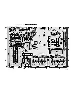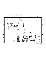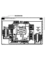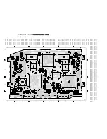
Electrical Alignments
EN 81
F21RE AB
8.
8.
Electrical Alignments
Index of this chapter:
1.
General Alignment Conditions
2.
Hardware Alignments
3.
Software Alignments
4.
Option Settings
Notes:
•
The Service Default Mode (SDM) and Service Alignment
Mode (SAM) are described in chapter 5. Menu navigation
is done with the CURSOR UP, DOWN, LEFT AND RIGHT
keys of the remote control transmitter.
•
Figures below can deviate slightly from the actual product,
due to different set designs.
8.1
General Alignment Conditions
Perform all electrical alignments under the following conditions:
•
Power supply voltage: 230 V_ac
±
10%, 50 Hz
±
5%.
•
Allow the set to warm up for approximately 20 minutes.
•
Voltages and waveforms are measured in relation to tuner
earth (with exception to the voltages on the primary side of
the power supply).
Caution: never use heatsinks as ground.
•
Test probe: Ri > 10 MOhm, Ci < 20 pF.
Before performing any alignments, set the receiver box to the
following settings:
•
Dynamic contrast: OFF (via the PICTURE menu).
•
Active control: OFF (via the remote control. The ACTIVE
CONTROL key is the key between the smart keys, and
toggles Active Control ON and OFF).
•
Smart Picture mode: ECO.
8.2
Hardware Alignments
8.2.1
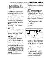
40.4 MHz Neighbour-channel Sound Trap Alignment
1.
Tune to a checker board test pattern (system PAL B/G with
a carrier frequency of 475.25 MHz).
2.
Connect an oscilloscope to pin 19 (CVBS out) of the
SCART1 connection and trigger line frequent.
3.
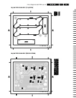
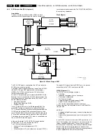
Align the coil L5103 (diagram K1) completely downwards
(see figure "SSP topview").
4.
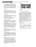
Align the coil upwards untill under- and overshoot arise at
the black/white and white/black transitions in the video
signal (see figure "Waveform sound trap alignment").
5.
Align the coil downwards again, untill above mentioned
under- and overshoot just disappears.
Figure 8-1 SSP top view
Figure 8-2 Waveform sound trap alignment
8.3
Software Alignments
Notes:
•
Alignments are stored automatically
•
Dealer option settings are stored automatically
•
Service option settings must be stored with the STORE
OPTIONS item in the top level SAM menu. It is not
necessary to turn the receiver box OFF and back ON in
order to store the values in NVM.
Put the set in SAM mode (see chapter 5). Now you can select
the following alignments:
1.
GENERAL:
–
LUMA GAIN
–
IF AFC
–
IF LPRIME AFC
–
TUNER AGC
–
BLEND INTENSITY
–
FBX TEST PATTERN
2.
DRIVE:
–
TEST PATTERN
–
RED
–
GREEN
–
BLUE
–
RED BL OFFSET
–
GREEN BL OFFSET
3.
LUM. DEL:
–
LUM. DELAY PAL BG
–
LUM. DELAY PAL I
–
LUM. DELAY SECAM
–
LUM. DELAY BYPASS
8.3.1
GENERAL Alignments
LUMA GAIN
This item has a fixed value of "3" (for EU/AP).
IF AFC
Connect the RF output of a video pattern generator to the
antenna input.
From the generator, supply a PAL B/G TV signal with a signal
strength of at least 1 mV and a frequency of 475.25 MHz.
Alignment procedure:
1.
Go to the INSTALL menu.
2.
Select MANUAL INSTALLATION.
3.
Tune the TV-set to the system and frequency described
above via SEARCH - 475.00 - OK.
4.
If the frequency shown in the FINE TUNE line (after the
SEARCH is completed) is between 475.18 MHz and
475.31 MHz, you do not need to realign the IF AFC.
CL 86532057_004a.AI
240798
1
2
3
0356
SAM
SDM
L5103
40.4 MHz
ALIGNMENT
SSP
Tuner
CL 86532057_006.AI
170798
Содержание F21RE
Страница 7: ...Directions for Use EN 7 F21RE AB 3 3 Directions for Use ...
Страница 8: ...Directions for Use EN 8 F21RE AB 3 ...
Страница 9: ...Directions for Use EN 9 F21RE AB 3 ...
Страница 10: ...Directions for Use EN 10 F21RE AB 3 ...
Страница 11: ...Directions for Use EN 11 F21RE AB 3 ...
Страница 12: ...Directions for Use EN 12 F21RE AB 3 ...
Страница 13: ...Directions for Use EN 13 F21RE AB 3 ...
Страница 14: ...Directions for Use EN 14 F21RE AB 3 ...
Страница 15: ...Directions for Use EN 15 F21RE AB 3 ...
Страница 16: ...Directions for Use EN 16 F21RE AB 3 ...
Страница 17: ...Directions for Use EN 17 F21RE AB 3 ...
Страница 18: ...Directions for Use EN 18 F21RE AB 3 ...
Страница 19: ...Directions for Use EN 19 F21RE AB 3 ...
Страница 20: ...Directions for Use EN 20 F21RE AB 3 ...
Страница 21: ...Directions for Use EN 21 F21RE AB 3 ...
Страница 22: ...Directions for Use EN 22 F21RE AB 3 ...
Страница 23: ...Directions for Use EN 23 F21RE AB 3 ...
Страница 24: ...Directions for Use EN 24 F21RE AB 3 ...
Страница 25: ......
Страница 114: ...Revision List EN 114 F21RE AB 11 11 Revision List First release ...

