background image

6

7

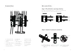
Step 3

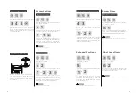
Latch Bolt Reversing

Latch bolt

1.  Push the latch bolt directional screw to the 

top.

2. Press the latch bolt and rotate it to 180°, then 

pull out the latch bolt.

3.  Push the latch bolt directional screw to the 

bottom.

4. Change the direction of the directional screw 

according to the inside and outside opening 

requirements.

(The directional screw must be installed on the 

inside of the door, that is, which side is equipped 

with directional screws, which side must be the 

inner body)

1

2

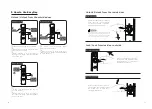
Installation Step

Tighten the four fixing screws on 

the mortise.

According to the thickness of the door, to 

appropriately cut  the mechanical key paddle, 

and choose the square shaft and the connecting 

screw  with proper length to fix the screw.

Attach the connecting bolts and 

the mechanical key paddles to the 

outer body, and place the pressure 

spring and the square shaft in the 

handle hole.

3

4

Fasten the mounting plate to the 

inside door and tighten the two 

fixing screws.

5

6

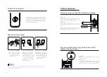
Change the direction of latch bolt to adapt to the direction of door opening 

from inside and outside. The inclined surface of the latch bolt opens toward the 

outside door is Inside-open, and the inclined surface of the latch bolt opens 

towards the inside is out-open.

Latch bolt slide switch

Directional screw

1.Use proper installation kit according to the door thickness.

2.The default installation kit is applicable to doors of 60-90mm thickness. If the thickness of your 

door is not within this range, please contact us.

The following installation steps apply to right-open doors. For left-open 

doors,please read [Pre-installation instructions] carefully and make needed 

adjustment.

Use the drilling template to drill 

the needed holes on the door and 

mount the mortise into the door.

Hook the upper and bottom poles 

when the mortise is inserted (this 

step is not equired when installing  

on the wooden door)

Pass the cable through the wire hole 

above the door. The mechanical key 

pad on the outer body and the square 

shaft are inserted into the two rotary 

holes on themortise, so that the outer 

body is close to the outside door.

Attention

Attention

Содержание EasyKey 7100DS

Страница 1: ......

Страница 2: ... batteries Unlock Unlock from Outside With Pin Code With Fingerprint Unlock from Inside With Handle Lock Locking from Outside Locking from Inside Deadlock from Inside Unlock with Mechanical Key 1 Important Info 02 2 EasyKey Installation 03 3 Get to know your EasyKey 09 4 How to set up your EasyKey 10 Security Warning Disposal of used products and Packaging List Exploded Views Pre installation Inst...

Страница 3: ...es not meet the safety requirements to power the product Do not connect the 2 poles of the batteries with metals to avoid short circuit which may lead to an explosion Please be sure any component replacement must be executed by Philips Philips authorized service center or professional technicians Do not use accessories or parts that have been produced by other manufacturers or have not been specif...

Страница 4: ...mutation Remove the two cross recessed countersunk screws on the escutcheon 1 Directly rotate the handle to 180 2 Lock the two cross recessed countersunk head screws back 3 1 2 6 7 3 4 5 6 7 8 9 10 11 12 13 Indoor Indoor Indoor Indoor Outdoor Outdoor Outdoor Outdoor Left in push Left Out Pull Right In Pull Right out pull Lock the Screw 6 M6 Mounting screw X2 7 Square shaft X2 8 Square Shaft Pressu...

Страница 5: ...g screws 5 6 Change the direction of latch bolt to adapt to the direction of door opening from inside and outside The inclined surface of the latch bolt opens toward the outside door is Inside open and the inclined surface of the latch bolt opens towards the inside is out open Latch bolt slide switch Directional screw 1 Use proper installation kit according to the door thickness 2 The default inst...

Страница 6: ...obs and mechanical keys to check if the components are connected properly 7 8 9 10 3 Get to know your EasyKey Outer Body Inner Body 5 1 2 4 6 3 1 2 3 5 6 Be sure to hide the extra cable in the door hole 7 8 9 10 4 1 2 3 4 5 6 7 8 9 10 Install the battery closethe battery cover and the innerbody bottom cover and the smart lock will be installed successfully Keypad Card Reader Mute Button Low batter...

Страница 7: ... press to confirm Press 2 to enter user settings then press 2 to add one time user password 2 2 Add one time password Key Tag Input There are 2 modes in the EasyKey General mode and Dual verification mode General Mode Dual verification Mode Unlock with any registered identity information Unlock with any two methods from PIN code card and fingerprint UserCode 1 Press key to return to the previous m...

Страница 8: ...r hearing a voice prompt of Succeeded press until you exitmastermode Press and input master Pin code then press to confirm Press 3 to enter into user info deletion then press 1 to delete user password and press 2 to delete all user passwords After hearing a voice prompt of Succeeded press until you exit master mode Press and input master Pin code then press to confirm Press 3 to enter into user de...

Страница 9: ...olume press 1 For low volume press 2 For mute mode press 3 After hearing a voice prompt of Succeeded press until you exit master mode Default volume High volume Press and input master Pin code then press to confirm Press 4 to enter system settings then press 3 to enter into verification mode porfolio Forsingleverificationmode pleasepress 1 For dual verification mode press 2 After hearing a voice p...

Страница 10: ...osing the door pull up the handle the latch bolt will be poped out so that door locking will be done Lock from outside Lock from inside 1 Place your registered finger properly on the sensor 2 After hearing a voice prompt of Door opened push or pull the handle to open the door 1 Place your registered key tag on the card reader 2 After hearing a voice prompt of Door opened push or pull the handle to...

Страница 11: ...ey cover is 90 perpendicular to the key and rotates the key cover with 90 toward the handle until it is close to the door surface Rotate the key cover down 180 so that the keycoverisparalleltothe ground Then rotate the key cover horizontally in the direction of the handletounlock Anti door view Switch Function This feature allows the handle to be locked from inside and the door lock cannot be open...

Страница 12: ...s off 2 Green Mute mode is on System lock indicator light Only under this verification mode the prompt will be shown Mute Button Functions The silent mode can be enabled with one button and the voice prompt is blocked when the door is opened which is suitable for scenes that do not disturb the rest of the family Usage 1 Voice mode switch to mute mode When the system wakes up press and hold the Mut...

Страница 13: ...e batteries immediately Low battery alarm reminds you to replace the batteries Triggering After waking up the system will run an automatic examination on the battery voltage If the voltage is too low there will be a voice prompt of Low battery Please replace all batteries Alarm method A voice prompt of Low battery Please replace all batteries during unlocking Turning off The alarm will be automati...

Страница 14: ...klijke Philips N V and are used under license This product has been manufactured by and is sold under the responsibility of Shenzhen Conex Intelligent Technology Co Ltd and Shenzhen Conex Intelligent Technology Co Ltd is the warrantor in relation to this product Version 2 0 ...

Отзывы: