Service Modes, Error Codes, and Fault Finding
EN 12
DPTV565 AA
5.
•
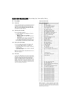
Line 3 : "OPT xxx xxx xxx xxx xxx xxx xxx xxx"; Option
bytes. Option bits control software and hardware
functionality. An option byte or option number represents
8 of those bits. Each option number is displayed as a
number between 0 and 255. The set may not work correctly
when an incorrect option code is set. See Service
Adjustments for more information on correct option settings
•
Line 4: "SYSTEM : AUTO"; Indicates which Colour and
sound system is installed for this preset: NTSC/PAL/
SECAM. Complaints that may be caused by an incorrect
system setting: no color / colours not correct / unstable
picture /noise in picture. To change the system setting of a
preset: Press the "MENU" button on the remote control
–
Select the INSTALL sub menu
–
Select the MANUAL STORE sub menu
–
Select and change the SYSTEM setting until picture
and sound are correct
–
Select the STORE menu item
•
Line 5 : "NO SIGNAL"; Indicates that the set is not
receiving an "ident" signal on the selected source. No or
bad antenna signal; connect a proper antenna signal.
Antenna not connected; connect the antenna. No channel
/ preset is stored at this program number; go to the
INSTALL menu and store a proper channel at this program
number. The tuner is faulty (in this case the CODES line
will contain number 13 or 16); check the tuner and replace/
repair if necessary.
Note: On some models (if the BM option is ON), BLUE
MUTE is displayed when no signal is received.
•
Line 6 : "TIMER ON " (Not Active on AP Units); Indicates
that the on/off timer is running.The following Complaints
may be caused by the activation of the sleep timer: The set
may turn on from standby or may switch to a different
channel without using either the remote control or the local
keyboard. To switch off the activation timer: Select
"TIMER" in the "FEATURE" menu. Select "ACTIVATE" in
the "TIMER" menu. Set to "OFF" with the left/right cursor
keys. Indicates that the on/off timer is running. The
following Complaints may be caused by the activation of
the sleep timer: The set may turn on from standby or may
switch to a different channel without using either the
remote control or the local keyboard.
•
Line 7: "CHANNEL BLOCKED"; Indicates that all channels
are locked except the selected channel.The following
complaints may be generated due to locked channels: TV
cannot be switched on from standby with the local
keyboard buttons. "CH+" and "CH-" buttons on local
keyboard do not function. To disable the LOCK feature:
Select "FEATURE" menu (with the Remote Control).
Select "LOCK" (with the Remote Control). Set to "OFF"
•
Line 8: "NOT PREFERED" (Not Active on AP Units);
Indicates that at least one channel is deleted as a preferred
channel (by default, all channels are skipped). Note that
"SKIPPED" will always be displayed in CSM unless all the
channels are not skipped. To add a channel as a selected
channel to the list of preferred channels: Select "INSTALL"
menu. Select "CHANNEL EDIT". Select "ADD/DELETE".
Set to "ADD" with the left/right cursor keys.
•
Line 9 : "HOTELMODE ON" (Not Active on AP Units);
Indicates that the Hotel mode has been activated.
•
Line 10 : "SOURCE :"Indicates which SOURCE is installed
for this preset. AV1, AV2, SVHS2, Channel number (8)
•
Line 11 : "SOUND"; Indicates which sound mode is
installed for this preset. Mono, Stereo, SAP, NICAM, L1,
L2, Virtual or Digital.
•
Line 12 : "VOLUME"; Value indicates level at CSM entry.
•
Line 13 : "BALANCE"; Value indicates level at CSM entry.
•
Line 14 : "HUE"; Value indicates level at CSM entry.
•
Line 15 : "COLOUR"; Value indicates level at CSM entry.
•
Line 16 : "BRIGHTNESS"; Value indicates level at CSM
entry.
•
Line 17 : "CONTRAST"; Value indicates level at CSM
entry.
How to Exit CSM
Use one of the following methods:
•
Press a key on the remote control transmitter with
exception of the 'CHANNEL', 'VOLUME' and digit (0-9)
keys)
•
Press the ‘POWER’ button on the remote control
transmitter or on the TV set.
5.3
Problems and Solving Tips (related to CSM)
Note: Below described problems are all related to the TV
settings. The procedures to change the value (or status) of the
different settings are described above. New value(s) are
automatically stored.
5.3.1
Picture Problems
Snowy/Noisy Picture
1.
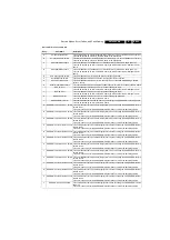
Check line 24 'Noise Figure'. In case the value is 127 or
higher, and the value is high on other programs, check the
aerial cable/aerial system.
2.
Check lines 11 'Sharpness' and 24 'Noise Figure'. In case
the value of line 11 is 3 or 4 and the value of line 24 is high
(127 or higher), decrease the 'Sharpness' value.
Picture too Dark
1.
Press 'Smart Picture' button on the RC-transmitter. In case
the picture improves, increase the 'Brightness' or the
'Contrast' value. The new value(s) are automatically stored
(in 'personal' pre-set) for all TV channels.
2.
Check line 7 'Brightness' and 8 'Contrast'. If the value of
line 7 is low (< 10) or the value of line 8 is low (< 10),
increase the 'Brightness' or the 'Contrast' value.
Picture too Bright
1.
Press 'Smart Picture' button on the RC-transmitter. In case
the picture improves, decrease the 'Brightness' or the
'Contrast' value. The new value(s) are automatically stored
(in 'personal' pre-set) for all TV channels.
2.
Check lines 7 'Brightness' and 6 'Contrast'. If the value of
line 7 is high (> 40) or the value of line 8 is high (> 50).
Decrease the 'Brightness' value or increase the 'Contrast'
value.
White Line around Picture Elements and Text
1.
Press 'Smart Picture' button on the Remote Control. In
case the picture improves, decrease the 'Sharpness' value.
The new value is automatically stored (in “personal” pre-
set) for all TV channels.
2.
Check line 11 'Sharpness'. Decrease the 'Sharpness'
value. The new value is automatically stored for all TV
channels.
No Picture
Check line 27 'Tuned bit'. In case the value is 'On', install the
required program again. Open the installation menu and
perform manual installation.
Blue Picture
No proper signal is received. Check the aerial cable/aerial
system.
Blue Picture and/or Unstable Picture
A scrambled or decoded signal is received.
Black and White Picture
Check line 9 'Colour'. In case the value is low (< 10), increase
the 'Colour' value. The new value is automatically stored for all
TV channels.
Содержание DPTV565 AA
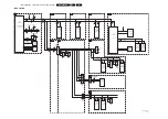
Страница 27: ...Circuit Diagrams and PWB Layouts 27 DPTV565 AA 7 Layout SSB Top Side E_15000_133 eps 191004 8204 000 6507 3 ...
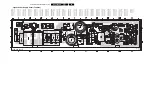
Страница 29: ...Circuit Diagrams and PWB Layouts 29 DPTV565 AA 7 Layout SSB Bottom Side E_15000_134 eps 191004 8204 000 6507 3 ...
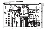
Страница 41: ...Circuit Diagrams and PWB Layouts 41 DPTV565 AA 7 Layout SSM Part 1 Bottom Side F_15020_011a eps 110305 Part 1 ...
Страница 42: ...42 DPTV565 AA 7 Circuit Diagrams and PWB Layouts Layout SSM Part 2 Bottom Side Part 2 F_15020_011b eps 110305 ...
Страница 43: ...Circuit Diagrams and PWB Layouts 43 DPTV565 AA 7 Layout SSM Part 3 Bottom Side F_15020_011c eps 110305 Part 3 ...
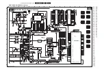
Страница 44: ...44 DPTV565 AA 7 Circuit Diagrams and PWB Layouts Layout SSM Part 4 Bottom Side F_15020_011d eps 110305 Part 4 ...
Страница 72: ...72 DPTV565 AA 7 Circuit Diagrams and PWB Layouts Personal Notes E_06532_013 eps 131004 ...
Страница 119: ...Revision List EN 119 DPTV565 AA 11 11 Revision List Manual xxxx xxx xxxx 0 First release ...


