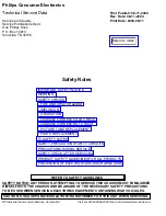


PREVENTION OF ELECTROSTATIC DISCHARGE (ESD)
Some semiconductor solid state devices can be damaged easily by static electricity. Such components
commonly are called Electrostatically Sensitive (ES) Devices, Examples of typical ES devices are
integrated circuits and some field-effect transistors and semiconductor "chip" components. The following
techniques should be used to help reduce the incidence of component damage caused by electrostatic
discharge (ESD).
1. Immediately before handling any semiconductor component or semiconductor-equipped assembly,
drain off any ESD on your body by touching a known earth ground. Alternatively, obtain and wear a
commercially available discharging ESD wrist strap, which should be removed for potential shock reasons
prior to applying power to the unit under test.
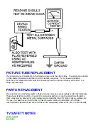
2. After removing an electrical assembly equipped with ES devices, place the assembly on a conductive
surface such as aluminum foil, to prevent electrostatic charge buildup or exposure of the assembly.
3. Use only a grounded-tip soldering iron to solder or unsolder ES devices.
4. Use only an anti-static solder removal device. Some solder removal devices not classified as "antistatic
(ESD protected)" can generate an electrical charge sufficient to damage ES devices.
5. Do not use freon·propelled chemicals. These can generate electrical charges sufficient to damage ES
devices.
6. Do not remove a replacement ES device from its protective package until immediately before you are
ready to install it (Most replacement ES devices are packaged with leads electrically shorted together by
conductive foam, aluminum foil or comparable conductive material).
7. Immediately before removing the protective material from the leads of a replacement ES device, touch
the protective material to the chassis or circuit assembly into which the device will be installed.
CAUTION
: Be sure no power is applied to the chassis or circuit and observe all other safety
precautions.
8. Minimize bodily motions when handling unpackaged replacement ES devices. (Otherwise harmless
motion such as the brushing together of your clothes fabric or the lifting of your feet from a carpeted
floor can generate static electricity (ESD) sufficient to damage an ES device.)
NOTE to CATV system Installer:
This reminder is provided to call the CATV system installer's attention to article 820-22 of the NEC that
provides guidelines for proper grounding and, in particular, specifies that the cable ground shall be
connected to the grounding system of the building, as close to the point of cable entry as practical.
Содержание 55PL9524/37
Страница 10: ...Page 9 of 15 2004 08 09 ...
Страница 23: ...Display The Main Cabinet Exploded View ...
Страница 34: ......
Страница 35: ......
Страница 36: ......
Страница 37: ...IIC BUS SIGNAL DIAGRAM ...
Страница 39: ......
Страница 40: ......
Страница 41: ......
Страница 42: ......
Страница 43: ......
Страница 44: ......
Страница 45: ......
Страница 46: ......
Страница 47: ......
Страница 48: ......
Страница 49: ......
Страница 50: ......
Страница 51: ......
Страница 52: ......
Страница 53: ......
Страница 54: ......
Страница 55: ......
Страница 56: ......
Страница 57: ......
Страница 58: ......
Страница 59: ......
Страница 60: ......
Страница 61: ......
Страница 62: ......
Страница 63: ......
Страница 64: ......
Страница 65: ......
Страница 66: ......
Страница 67: ......
Страница 68: ......
Страница 69: ......
Страница 70: ......
Страница 71: ......
Страница 72: ......
Страница 73: ......
Страница 74: ......
Страница 75: ......
Страница 76: ......
Страница 77: ......
Страница 78: ......
Страница 79: ......
Страница 80: ......
Страница 81: ......
Страница 82: ......
Страница 83: ......
Страница 84: ......
Страница 86: ...Refer to the next page for Bottom Side View W INPUT POWER PANEL Top View Return to Circuit Board TOC ...
Страница 87: ... W INPUT POWER PANEL Bottom View Return to Circuit Board TOC ...
Страница 89: ... U1 MAIN POWER PANEL Bottom View Return to Circuit Board TOC ...
Страница 90: ...Refer to the next page for Bottom Side View K SYSTEM BOARD Top View Return to Circuit Board TOC ...
Страница 91: ... K SYSTEM BOARD Bottom View Return to Circuit Board TOC ...
Страница 92: ...Refer to the next page for Bottom Side View B SSB PANEL Top View Return to Circuit Board TOC ...
Страница 93: ... B SSB PANEL Bottom View Return to Circuit Board TOC ...
Страница 94: ...Refer to the next page for Bottom Side View SL SCALER PANEL Top View Return to Circuit Board TOC ...
Страница 95: ... SL SCALER PANEL Bottom View Return to Circuit Board TOC ...
Страница 96: ...Refer to the next page for Bottom Side View F DW PIP PANEL Top View Return to Circuit Board TOC ...
Страница 97: ... F DW PIP PANEL Bottom View Return to Circuit Board TOC ...
Страница 98: ...Refer to the next page for Bottom Side View CB1 3D COMB FILTER PANEL Top View Return to Circuit Board TOC ...
Страница 99: ... CB1 3D COMB FILTER PANEL Bottom View Return to Circuit Board TOC ...
Страница 100: ...Refer to the next page for Bottom Side View V REAR JACK PANEL Top View Return to Circuit Board TOC ...
Страница 101: ... V REAR JACK PANEL Bottom View Return to Circuit Board TOC ...
Страница 102: ...Refer to the next page for Bottom Side View O1 SIDE JACK PANEL Top View Return to Circuit Board TOC ...
Страница 103: ... O1 SIDE JACK PANEL Bottom View Return to Circuit Board TOC ...
Страница 104: ...Refer to the next page for Bottom Side View LS LED SENSOR PANEL Top View Return to Circuit Board TOC ...
Страница 105: ... LS LED SENSOR PANEL Bottom View Return to Circuit Board TOC ...
Страница 106: ...Refer to the next page for Bottom Side View P1 LED KEYBOARD PANEL Top View Return to Circuit Board TOC ...
Страница 107: ... P1 LED KEYBOARD PANEL Bottom View Return to Circuit Board TOC ...
Страница 108: ...Refer to the next page for Bottom Side View TS1 THERMAL SENSOR PANEL Top View Return to Circuit Board TOC ...
Страница 109: ... TS1 THERMAL SENSOR PANEL Bottom View Return to Circuit Board TOC ...
Страница 110: ...Refer to the next page for Bottom Side View AA1 AUDIO AMPLIFIER PANEL Top View Return to Circuit Board TOC ...
Страница 111: ... AA1 AUDIO AMPLIFIER PANEL Bottom View Return to Circuit Board TOC ...
Страница 112: ...Refer to the next page for Bottom Side View Return to Circuit Board TOC ...
Страница 113: ...Return to Circuit Board TOC ...
Страница 115: ... 7665 Page 1 P1 P2 P3 P4 P5 P6 P7 C1 C2 C3 C4 C5 C6 F30 F31 F32 L14 L15 L16 V31 ...
Страница 116: ... 7665 Page 2 V32 F14 I 6 L 8 V 1 V 2 V 6 V 7 V 8 V 9 V10 L1 L2 L3 L4 L5 L6 L7 L8 L9 ...
Страница 117: ... 7665 Page 3 F17 F18 F19 F20 L12 V19 V20 V21 V28 V29 V30 B51 B52 B53 B54 B55 B57 B58 B60 A15 ...
Страница 118: ... 7665 Page 4 B65 B66 B67 B74 B75 B76 F105 F111 F112 F113 F131 F132 F133 F134 F136 F137 F281 F284 F301 F306 ...
Страница 119: ... 7665 Page 5 F311 F312 F313 F351 F358 F392 F509 F523 F558 F559 F584 F595 F726 F727 F728 F778 F781 F793 F822 F825 ...
Страница 120: ... 7665 Page 6 F826 F827 F828 F855 F856 F857 F858 F21 F22 F23 F24 F25 F26 F27 L17 L18 L19 V17A V18A F1 ...
Страница 121: ... 7665 Page 7 F2 F14 F15 F16 F17 F18 V19A V20A F 3 F 4 F 5 F 6 F 7 F 8 F 9 F10 F11 F12 F13 A1 ...
Страница 122: ... 7665 Page 8 A2 A3 A4 A5 A6 A7 A8 ...
Страница 124: ...Overall Cabinet Exploded View Page 1 of 5 ...
Страница 125: ...Cabinet Detail 1 Exploded View Page 2 of 5 ...
Страница 126: ...Cabinet Detail 2 Exploded View Page 3 of 5 ...
Страница 127: ...Power Supply Assembly Exploded View Page 4 of 5 ...
Страница 128: ...Signal Assembly Exploded View Page 5 of 5 ...