
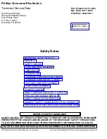


1. Be sure procedures and instructions to all your service personnel cover the subject of X-radiation.
Potential sources of X-rays in TV receivers are the picture tube and the high voltage circuits. The basic
precaution which must be exercised is to keep the high voltage at the factory recommended level.
2. To avoid possible exposure to X-radiation and electrical shock, only the manufacturer's specified
anode connectors must be used.
3. It is essential that the service technician has an accurate HV meter available at all times. The
calibration of this meter should be checked periodically against a reference standard.
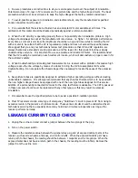
4. When the HV circuitry is operating properly there is no possibility of an X-radiation problem. High
voltage should always be kept at the manufacturer's rated value - no higher - for optimum performance.
Every time a color set is serviced, the brightness should be run up and down while monitoring the HV
with a meter to be certain that the HV is regulated correctly and does not exceed the specified value.
We suggest that you and your technicians review test procedures so that HV and HV regulation are
always checked as a standard servicing procedure, and the reason for this prudent routine is clearly
understood by everyone. It is important to use an accurate and reliable HV meter. It is recommended
that the HV reading be recorded on each customer's invoice, which will demonstrate a proper concern for
the customer's safety.
5. When troubleshooting and making test measurements in a receiver with a problem of excessive high
voltage, reduce the line voltage by means of a Variac to bring the HV into acceptable limits while
troubleshooting. Do not operate the chassis longer than necessary to locate the cause of the excessive
HV.
6. New picture tubes are specifically designed to withstand higher operating voltages without creating
undesirable X-radiation. It is strongly recommended that any shop test fixture which is to be used with
the new higher voltage chassis be equipped with one of the new type tubes designed for this service.
Addition of a permanently connected HV meter to the shop test fixture is advisable. The CRT types used
in these new sets should never be replaced with any other types, as this may result in excessive
X-radiation.
7. It is essential to use the specified picture tube to avoid a possible X-radiation problem.
8. Most TV receivers contain some type of emergency "Hold Down" circuit to prevent HV from rising to
excessive levels in the presence of a failure mode. These various circuits should be understood by all
technicians servicing them, especially since many hold down circuits are inoperative as long as the
receiver performs normally.
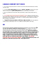
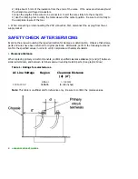
LEAKAGE CURRENT COLD CHECK
1. Unplug the ac line cord and connect a jumper between the two prongs of the plug.
2. Turn on the power switch.
3. Measure the resistance value between the jumpered ac plug and all exposed cabinet parts of the
receiver, such as screw heads, antennas, and control shafts. When the exposed metallic part has a
return path to the chassis, the reading should be between 1 megohm and 5.2 megohms. When the
exposed metal does not have a return path to the chassis, the reading must be infinity. Remove the
jumper from the ac line cord.
Содержание 55PL9524/37
Страница 10: ...Page 9 of 15 2004 08 09 ...
Страница 23: ...Display The Main Cabinet Exploded View ...
Страница 34: ......
Страница 35: ......
Страница 36: ......
Страница 37: ...IIC BUS SIGNAL DIAGRAM ...
Страница 39: ......
Страница 40: ......
Страница 41: ......
Страница 42: ......
Страница 43: ......
Страница 44: ......
Страница 45: ......
Страница 46: ......
Страница 47: ......
Страница 48: ......
Страница 49: ......
Страница 50: ......
Страница 51: ......
Страница 52: ......
Страница 53: ......
Страница 54: ......
Страница 55: ......
Страница 56: ......
Страница 57: ......
Страница 58: ......
Страница 59: ......
Страница 60: ......
Страница 61: ......
Страница 62: ......
Страница 63: ......
Страница 64: ......
Страница 65: ......
Страница 66: ......
Страница 67: ......
Страница 68: ......
Страница 69: ......
Страница 70: ......
Страница 71: ......
Страница 72: ......
Страница 73: ......
Страница 74: ......
Страница 75: ......
Страница 76: ......
Страница 77: ......
Страница 78: ......
Страница 79: ......
Страница 80: ......
Страница 81: ......
Страница 82: ......
Страница 83: ......
Страница 84: ......
Страница 86: ...Refer to the next page for Bottom Side View W INPUT POWER PANEL Top View Return to Circuit Board TOC ...
Страница 87: ... W INPUT POWER PANEL Bottom View Return to Circuit Board TOC ...
Страница 89: ... U1 MAIN POWER PANEL Bottom View Return to Circuit Board TOC ...
Страница 90: ...Refer to the next page for Bottom Side View K SYSTEM BOARD Top View Return to Circuit Board TOC ...
Страница 91: ... K SYSTEM BOARD Bottom View Return to Circuit Board TOC ...
Страница 92: ...Refer to the next page for Bottom Side View B SSB PANEL Top View Return to Circuit Board TOC ...
Страница 93: ... B SSB PANEL Bottom View Return to Circuit Board TOC ...
Страница 94: ...Refer to the next page for Bottom Side View SL SCALER PANEL Top View Return to Circuit Board TOC ...
Страница 95: ... SL SCALER PANEL Bottom View Return to Circuit Board TOC ...
Страница 96: ...Refer to the next page for Bottom Side View F DW PIP PANEL Top View Return to Circuit Board TOC ...
Страница 97: ... F DW PIP PANEL Bottom View Return to Circuit Board TOC ...
Страница 98: ...Refer to the next page for Bottom Side View CB1 3D COMB FILTER PANEL Top View Return to Circuit Board TOC ...
Страница 99: ... CB1 3D COMB FILTER PANEL Bottom View Return to Circuit Board TOC ...
Страница 100: ...Refer to the next page for Bottom Side View V REAR JACK PANEL Top View Return to Circuit Board TOC ...
Страница 101: ... V REAR JACK PANEL Bottom View Return to Circuit Board TOC ...
Страница 102: ...Refer to the next page for Bottom Side View O1 SIDE JACK PANEL Top View Return to Circuit Board TOC ...
Страница 103: ... O1 SIDE JACK PANEL Bottom View Return to Circuit Board TOC ...
Страница 104: ...Refer to the next page for Bottom Side View LS LED SENSOR PANEL Top View Return to Circuit Board TOC ...
Страница 105: ... LS LED SENSOR PANEL Bottom View Return to Circuit Board TOC ...
Страница 106: ...Refer to the next page for Bottom Side View P1 LED KEYBOARD PANEL Top View Return to Circuit Board TOC ...
Страница 107: ... P1 LED KEYBOARD PANEL Bottom View Return to Circuit Board TOC ...
Страница 108: ...Refer to the next page for Bottom Side View TS1 THERMAL SENSOR PANEL Top View Return to Circuit Board TOC ...
Страница 109: ... TS1 THERMAL SENSOR PANEL Bottom View Return to Circuit Board TOC ...
Страница 110: ...Refer to the next page for Bottom Side View AA1 AUDIO AMPLIFIER PANEL Top View Return to Circuit Board TOC ...
Страница 111: ... AA1 AUDIO AMPLIFIER PANEL Bottom View Return to Circuit Board TOC ...
Страница 112: ...Refer to the next page for Bottom Side View Return to Circuit Board TOC ...
Страница 113: ...Return to Circuit Board TOC ...
Страница 115: ... 7665 Page 1 P1 P2 P3 P4 P5 P6 P7 C1 C2 C3 C4 C5 C6 F30 F31 F32 L14 L15 L16 V31 ...
Страница 116: ... 7665 Page 2 V32 F14 I 6 L 8 V 1 V 2 V 6 V 7 V 8 V 9 V10 L1 L2 L3 L4 L5 L6 L7 L8 L9 ...
Страница 117: ... 7665 Page 3 F17 F18 F19 F20 L12 V19 V20 V21 V28 V29 V30 B51 B52 B53 B54 B55 B57 B58 B60 A15 ...
Страница 118: ... 7665 Page 4 B65 B66 B67 B74 B75 B76 F105 F111 F112 F113 F131 F132 F133 F134 F136 F137 F281 F284 F301 F306 ...
Страница 119: ... 7665 Page 5 F311 F312 F313 F351 F358 F392 F509 F523 F558 F559 F584 F595 F726 F727 F728 F778 F781 F793 F822 F825 ...
Страница 120: ... 7665 Page 6 F826 F827 F828 F855 F856 F857 F858 F21 F22 F23 F24 F25 F26 F27 L17 L18 L19 V17A V18A F1 ...
Страница 121: ... 7665 Page 7 F2 F14 F15 F16 F17 F18 V19A V20A F 3 F 4 F 5 F 6 F 7 F 8 F 9 F10 F11 F12 F13 A1 ...
Страница 122: ... 7665 Page 8 A2 A3 A4 A5 A6 A7 A8 ...
Страница 124: ...Overall Cabinet Exploded View Page 1 of 5 ...
Страница 125: ...Cabinet Detail 1 Exploded View Page 2 of 5 ...
Страница 126: ...Cabinet Detail 2 Exploded View Page 3 of 5 ...
Страница 127: ...Power Supply Assembly Exploded View Page 4 of 5 ...
Страница 128: ...Signal Assembly Exploded View Page 5 of 5 ...


