
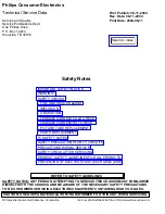


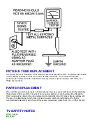


PARTS REPLACEMENT
FIRE AND SHOCK HAZARD
1. Be sure all components are positioned in such a way as to avoid the possibility of adjacent
component shorts. This is especially important on those chassis which are transported to and from the
service shop.
2. Never release a repaired unit unless all protective devices such as insulators, barriers, covers, strain
reliefs, and other hardware have been installed in accordance with the original design.
3. Soldering and wiring must be inspected to locate possible cold solder joints, solder splashes, sharp
solder points, frayed leads, pinched leads, or damaged insulation (including the ac cord). Be certain to
remove loose solder balls and all other loose foreign particles.
4. Check across-the-line components and other components for physical evidence of damage or
deterioration and replace if necessary. Follow original layout, lead length, and dress.
5. No lead or component should touch a receiving tube or a resistor rated at 1 watt or more. Lead
tension around protruding metal surfaces or edges must be avoided.
6. Critical components having special safety characteristics are identified with an
'S'
by the Ref. No. in
the parts list and enclosed within a broken line* (where several critical components are grouped in one
area) along with the safety symbol
on the schematic diagrams and /or exploded views.
7. When servicing any unit, always use a separate isolation transformer for the chassis. Failure to use a
separate isolation transformer may expose you to possible shock hazard, and may cause damage to
servicing instruments.
8. Many electronic products use a polarized ac line cord (one wide pin on the plug). Defeating this
safety feature may create a potential hazard to the servicer and the user. Extension cords which do not
incorporate the polarizing feature should never be used.
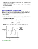
9. After reassembly of the unit, always perform an
ac leakage test
or resistance test from the line cord to
all exposed metal parts of the cabinet. Also, check all metal control shafts (with knobs removed),
antenna terminals, handles, screws, etc., to be sure the unit may be safely operated without danger of
electrical shock.
* Broken line ____ _ ____ _ ____ _ ____
IMPLOSION
1. All picture tubes used in current model receivers are equipped with an integral implosion system.
Care should always be used, and safety glasses worn, whenever handling any picture tube. Avoid
scratching or otherwise damaging the picture tube during installation.
2. Use only replacement tubes specified by the manufacturer.
X-RADIATION
Содержание 55PL9524/37
Страница 10: ...Page 9 of 15 2004 08 09 ...
Страница 23: ...Display The Main Cabinet Exploded View ...
Страница 34: ......
Страница 35: ......
Страница 36: ......
Страница 37: ...IIC BUS SIGNAL DIAGRAM ...
Страница 39: ......
Страница 40: ......
Страница 41: ......
Страница 42: ......
Страница 43: ......
Страница 44: ......
Страница 45: ......
Страница 46: ......
Страница 47: ......
Страница 48: ......
Страница 49: ......
Страница 50: ......
Страница 51: ......
Страница 52: ......
Страница 53: ......
Страница 54: ......
Страница 55: ......
Страница 56: ......
Страница 57: ......
Страница 58: ......
Страница 59: ......
Страница 60: ......
Страница 61: ......
Страница 62: ......
Страница 63: ......
Страница 64: ......
Страница 65: ......
Страница 66: ......
Страница 67: ......
Страница 68: ......
Страница 69: ......
Страница 70: ......
Страница 71: ......
Страница 72: ......
Страница 73: ......
Страница 74: ......
Страница 75: ......
Страница 76: ......
Страница 77: ......
Страница 78: ......
Страница 79: ......
Страница 80: ......
Страница 81: ......
Страница 82: ......
Страница 83: ......
Страница 84: ......
Страница 86: ...Refer to the next page for Bottom Side View W INPUT POWER PANEL Top View Return to Circuit Board TOC ...
Страница 87: ... W INPUT POWER PANEL Bottom View Return to Circuit Board TOC ...
Страница 89: ... U1 MAIN POWER PANEL Bottom View Return to Circuit Board TOC ...
Страница 90: ...Refer to the next page for Bottom Side View K SYSTEM BOARD Top View Return to Circuit Board TOC ...
Страница 91: ... K SYSTEM BOARD Bottom View Return to Circuit Board TOC ...
Страница 92: ...Refer to the next page for Bottom Side View B SSB PANEL Top View Return to Circuit Board TOC ...
Страница 93: ... B SSB PANEL Bottom View Return to Circuit Board TOC ...
Страница 94: ...Refer to the next page for Bottom Side View SL SCALER PANEL Top View Return to Circuit Board TOC ...
Страница 95: ... SL SCALER PANEL Bottom View Return to Circuit Board TOC ...
Страница 96: ...Refer to the next page for Bottom Side View F DW PIP PANEL Top View Return to Circuit Board TOC ...
Страница 97: ... F DW PIP PANEL Bottom View Return to Circuit Board TOC ...
Страница 98: ...Refer to the next page for Bottom Side View CB1 3D COMB FILTER PANEL Top View Return to Circuit Board TOC ...
Страница 99: ... CB1 3D COMB FILTER PANEL Bottom View Return to Circuit Board TOC ...
Страница 100: ...Refer to the next page for Bottom Side View V REAR JACK PANEL Top View Return to Circuit Board TOC ...
Страница 101: ... V REAR JACK PANEL Bottom View Return to Circuit Board TOC ...
Страница 102: ...Refer to the next page for Bottom Side View O1 SIDE JACK PANEL Top View Return to Circuit Board TOC ...
Страница 103: ... O1 SIDE JACK PANEL Bottom View Return to Circuit Board TOC ...
Страница 104: ...Refer to the next page for Bottom Side View LS LED SENSOR PANEL Top View Return to Circuit Board TOC ...
Страница 105: ... LS LED SENSOR PANEL Bottom View Return to Circuit Board TOC ...
Страница 106: ...Refer to the next page for Bottom Side View P1 LED KEYBOARD PANEL Top View Return to Circuit Board TOC ...
Страница 107: ... P1 LED KEYBOARD PANEL Bottom View Return to Circuit Board TOC ...
Страница 108: ...Refer to the next page for Bottom Side View TS1 THERMAL SENSOR PANEL Top View Return to Circuit Board TOC ...
Страница 109: ... TS1 THERMAL SENSOR PANEL Bottom View Return to Circuit Board TOC ...
Страница 110: ...Refer to the next page for Bottom Side View AA1 AUDIO AMPLIFIER PANEL Top View Return to Circuit Board TOC ...
Страница 111: ... AA1 AUDIO AMPLIFIER PANEL Bottom View Return to Circuit Board TOC ...
Страница 112: ...Refer to the next page for Bottom Side View Return to Circuit Board TOC ...
Страница 113: ...Return to Circuit Board TOC ...
Страница 115: ... 7665 Page 1 P1 P2 P3 P4 P5 P6 P7 C1 C2 C3 C4 C5 C6 F30 F31 F32 L14 L15 L16 V31 ...
Страница 116: ... 7665 Page 2 V32 F14 I 6 L 8 V 1 V 2 V 6 V 7 V 8 V 9 V10 L1 L2 L3 L4 L5 L6 L7 L8 L9 ...
Страница 117: ... 7665 Page 3 F17 F18 F19 F20 L12 V19 V20 V21 V28 V29 V30 B51 B52 B53 B54 B55 B57 B58 B60 A15 ...
Страница 118: ... 7665 Page 4 B65 B66 B67 B74 B75 B76 F105 F111 F112 F113 F131 F132 F133 F134 F136 F137 F281 F284 F301 F306 ...
Страница 119: ... 7665 Page 5 F311 F312 F313 F351 F358 F392 F509 F523 F558 F559 F584 F595 F726 F727 F728 F778 F781 F793 F822 F825 ...
Страница 120: ... 7665 Page 6 F826 F827 F828 F855 F856 F857 F858 F21 F22 F23 F24 F25 F26 F27 L17 L18 L19 V17A V18A F1 ...
Страница 121: ... 7665 Page 7 F2 F14 F15 F16 F17 F18 V19A V20A F 3 F 4 F 5 F 6 F 7 F 8 F 9 F10 F11 F12 F13 A1 ...
Страница 122: ... 7665 Page 8 A2 A3 A4 A5 A6 A7 A8 ...
Страница 124: ...Overall Cabinet Exploded View Page 1 of 5 ...
Страница 125: ...Cabinet Detail 1 Exploded View Page 2 of 5 ...
Страница 126: ...Cabinet Detail 2 Exploded View Page 3 of 5 ...
Страница 127: ...Power Supply Assembly Exploded View Page 4 of 5 ...
Страница 128: ...Signal Assembly Exploded View Page 5 of 5 ...


