Service Modes, Error Codes, and Fault Finding
EN 22
LC8.1U LA
5.
5.2.3
Service Alignment Mode (SAM)
Purpose
•
To change option settings.
•
To display / clear the error code buffer.
•
To perform alignments.
Specifications
•
Operation hours counter (maximum five digits displayed).
•
Software version, error codes, and option settings display.
•
Error buffer clearing.
•
Option settings.
•
Software alignments (White Tone).
•
NVM Editor.
•
Set screen mode to full screen (all content is visible).
How to Activate
To activate SAM, use one of the following methods:
•
Press the following key sequence on the remote control
transmitter: “062596” directly followed by the OSD/
STATUS/INFO/i+ button (it depends on region which
button is present on the RC). Do not allow the display to
time out between entries while keying the sequence.
•
Or via ComPair.
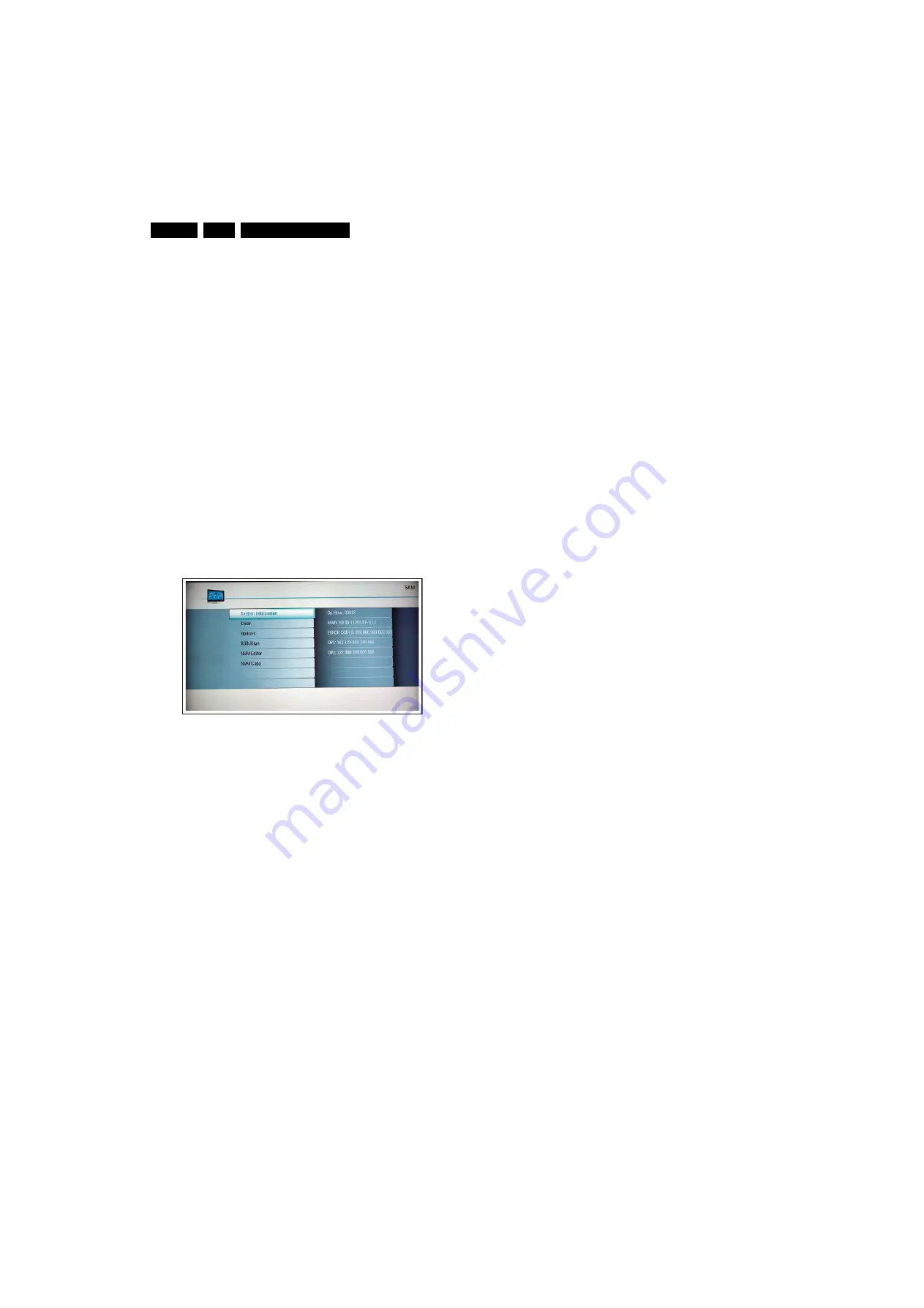
After entering SAM, the following screen is visible, with SAM in
the upper right corner of the screen to indicate that the
television is in Service Alignment Mode.
Figure 5-4 SAM menu
Menu explanation:
1.
System Information:
•
Op. Hour. This represents the life timer. The timer
counts normal operation hours, but does not count
Stand-by hours.
•
MAIN SW ID. See paragraph “Service Modes” ->
“General” -> “Software Identification, Version, and
Cluster” for the SW name definition.
•
ERROR CODES. Shows all errors detected since the
last time the buffer was erased. Five errors possible.
•
OP1 / OP2. Used to read-out the option bytes. See
“Options” in the Alignments section for a detailed
description. Ten codes are possible.
2.
Clear. Erases the contents of the error buffer. Select the
CLEAR menu item and press the MENU RIGHT key. The
content of the error buffer is cleared.
3.
Options. To set the option bits. See “Options” in the
“Alignments” chapter for a detailed description.
4.
RGB Align. To align the White Tone. See “White Tone” in
the “Alignments” chapter for a detailed description.
5.
NVM Editor. To change the NVM data in the television set.
See also paragraph “Fault Finding and Repair Tips”.
6.
NVM Copy. Gives the possibility to copy/load the NVM file
to/from an USB stick.
Important: NVM data copied to a USB memory device is
named “TV2USB.bin”. When copied back to a TV, the file
first must be renamed to “USB2TV.bin”.
How to Navigate
•
In the SAM menu, select menu items with the UP/DOWN
keys on the remote control transmitter. The selected item
will be indicated. When not all menu items fit on the screen,
use the UP/DOWN keys to display the next / previous
menu items.
•
With the LEFT/RIGHT keys, it is possible to:
–
Activate the selected menu item.
–
Change the value of the selected menu item.
–
Activate the selected sub menu.
•
When you press the MENU button twice while in top level
SAM, the set will switch to the normal user menu (with the
SAM mode still active in the background). To return to the
SAM menu press the MENU button.
•
The “OSD/STATUS/INFO/i+” key from the user remote will
toggle the OSD “on/off” with “SAM” OSD remaining always
“on”.
•
Press the following key sequence on the remote control
transmitter: “062596” directly followed by the MENU button
to switch to SDM (do not allow the display to time out
between entries while keying the sequence).
How to Store SAM Settings
To store the settings changed in SAM mode (except the
OPTIONS and RGB ALIGN settings), leave the top level SAM
menu by using the POWER button on the remote control
transmitter or the television set. The mentioned exceptions
must be stored separately via the STORE button.
How to Exit
Switch the set to STANDBY by pressing the mains button on
the remote control transmitter or the television set.
Note:
•
When the TV is switched “off” by a power interrupt while in
SAM, the TV will show up in “normal operation mode” as
soon as the power is supplied again. The error buffer will
not be cleared.
•
In case the set is in Factory mode by accident (with “F”
displayed on screen), by pressing and hold “VOL-“ and
“CH-” together should leave Factory mode.
H_17740_025.eps
230108
Содержание 32PFL3403D/85
Страница 65: ...Circuit Diagrams and PWB Layouts 65 LC8 1U LA 7 Layout Small Signal Board Part 1 Bottom Side Part 1 ...
Страница 67: ...Circuit Diagrams and PWB Layouts 67 LC8 1U LA 7 Layout Small Signal Board Part 3 Bottom Side Part 3 ...
Страница 74: ...74 LC8 1U LA 7 Circuit Diagrams and PWB Layouts Personal Notes E_06532_013 eps 131004 ...
Страница 96: ...www s manuals com ...


