background image

Go to cover page

202P7 CRT

21

OSD Adjustments (Continued)

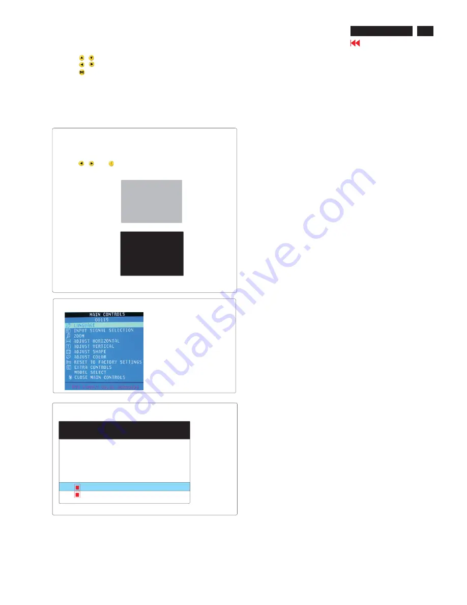
To access BURN IN mode
First of all, monitor displays an image.
1. Disconnect the video cable(interface cable).
2. Turn off monitor
3. Press

and

simultaneously on the front control panel,

then the BURN IN mode comes on the screen of monitor as below.

50 seconds around

5 second around

repeat

4. Reconnect the video cable, then return the normal image.

SERVICE MODE (indication-factory mode)

00119: stand for
1. Using 10 hours already
2. Turn on/off 10 times.
3. Using several hours

+ turn on/off monitors.

Default setting of MODEL SELECT (Do not change it.)

MODEL SELECT

RESERVE

RESERVE
RESERVE

130K 202P7 SDI
SWDDC

RESERVE

<-------------------------

4. Using

: to select OSD menu.

5. Using

: to increase or decrease the setting.

6. Using

: to access/confirm the selection.

To leave factory mode

7. After alignment of factory mode, turn off monitor(if you do not run

off monitor, the OSD menu is always at the factory mode), then turn
on monitor again (at this moment, the OSD menu goes back to user
mode.)

Содержание 202P70/00

Страница 1: ...e Diagram C B A 49 50 Key Control Diagram C B A 51 MHR Diagram C B A 52 Waveform Diagram 53 56 Exploded View 57 Spare Parts List 58 62 Recommended Parts List 63 General Product Specification 64 84 Repair Tips 86 Safety Test Requirements 87 Warning and Notes 88 Different Parts List 89 Color Adjustments 85 REFER TO BACK COVER FOR IMPORTANT SAFETY GUIDELINES CAUTION USE A SEPARATE ISOLATION TRANSFORM...

Страница 2: ...er his safety nor the safe operation of the equipment will be jeopardized by the service method selected Hereafter throughout this manual Philips Consumer Electronics Company will be referred to as Philips Critical components having special safety characteristics are identified with a by the Ref No in the parts list and enclosed within a broken line where several critical components are grouped in...

Страница 3: ...d 8 Blue video ground 9 5V 10 Logic ground 11 Id bit Connected to pin 10 12 Serial data line SDA 13 H H V Sync 14 V Sync VCLK for DDC 15 Data clock line SCL 2 BNC input connectors rear 1 Red video input 2 Green video input or Green video with Sync On Green input 3 Blue video input 4 H H V sync 5 V sync 3 Signal interface Detachable 1 5M 15Pins pantone 661C color with icons D sub male at both ends ...

Страница 4: ...provides user friendliness and ease of use when operating the monitor On the front controls of your monitor once you press button the On Screen Display OSD Main Controls window will pop up and you can now start making adjustments to your monitor s various features Use the or the buttons to make your adjustments within Description of the On Screen Display What is the On Screen Display Basic and sim...

Страница 5: ...zero beam current for SDI 21 DFT tube Glue fix the R3698VR 4 1 2 Monitor the following auxiliary voltages 8 0V SOURCE ACROSS C2362 8 0V 0 5 VDC 5 0V SOURCE ACROSS C2143 5 0V 0 5 VDC 12 0V SOURCE ACROSS C2361 12 0V 0 5 VDC 15 0V SOURCE ACROSS C2134 15 1V 1 0 VDC 15 0V SOURCE ACROSS C2137 15 4V 1 0 VDC 6 3V SOURCE ACROSS D6143 6 1V 0 5 VDC 230 0V SOURCE ACROSS C2131 230 0V 0 5 VDC 80 0V SOURCE ACROS...

Страница 6: ...rom CAA alignment Program according to software approval Sheet 140 139 7 5 3 Switch on AUTO the auto calibration function after finish all alignment items 7 6 Smart Mode color adjustment This process only can be taken One test circuit should be added to up high the EHT voltage during the adjustment 270K 3697 68K 1M SW 3698 20K Adjust 1Mohm pot meter decrease the resistance from Max position gradua...

Страница 7: ...5 10 58 5 61 5 1024 768 75 0 140 11 61 5 65 0 1280 1024 60 0 140 12 65 0 70 0 1024 768 85 0 150 13 70 0 73 0 1125 900 76 0 155 14 73 0 76 0 1600 1200 60 0 155 15 76 0 80 6 1152 864 85 0 165 16 80 6 82 5 1600 1200 65 0 165 17 82 5 84 8 1792 1344 60 0 165 18 84 8 88 5 1600 1200 70 0 165 19 88 8 92 5 1280 1024 85 0 175 20 92 5 98 0 1600 1200 75 0 175 21 98 0 102 0 1600 1200 80 0 175 22 102 0 110 0 17...

Страница 8: ...he alignment result DAC values of inspection mode timing table No 30 into preload mode timing table No 29 28 27 25 and 24 8 2 20 Copy the alignment result DAC values of alignment mode timing table No 35 into preload mode timing table No 14 8 2 21 Copy the alignment result DAC values of inspection mode timing table No 21 into preload mode timing table No 20 26 and 36 8 2 22 Fill up all alignment re...

Страница 9: ...s shown Fig 3 2 Video panel Disconnect the wire between metal shield of video panel and CRT neck as shown in Fig 6 Disconnect the CRT grounding from Video panel Remove and grounding wire in Fig 6 3 Main board connector in Fig 7 Disconnect york wire Disconnect rotation connector Disconnect control board connector Remove Screw for fixed I F cable Remove signal connector Remove degaussing wire connec...

Страница 10: ...Remove 4 screws for disconnect the Bottom tray as Fig 8 Remove the bottom tray on press right and left side clip from fig 8 to fig 9 5 SERVICE POSITION reconnect connectors some wires and panels chassis service position can be available for DC AC measurement as shown in Fig 9 Fig 7 Fig 8 Fig 9 ...

Страница 11: ... monitor cable has bent pins Make sure the computer Power button is on Make sure the monitor cable is properly connected to your computer Also refer to the Quick Start Guide Check to see if the monitor cable has bent pins Make sure the computer is turned on If you are using a non VESA DDC standard video card turn the DDC1 2B feature Off The picture may need degaussing Remove any nearby magnetic ob...

Страница 12: ...w the steps under LANGUAGE LANGUAGE The ON SCREEN DISPLAY shows its setting in one of eight languages The default is English but you can select French Spanish German Italian simplify Chinese Korea or Portuguese 1 Press the button the monitor The MAIN CONTROLS window appears LANGUAGE should be highlighted 2 Press the button again The LANGUAGE window appears INPUT SIGNALSELECTION 3 Press the button ...

Страница 13: ...p After returning to MAIN CONTROLS To continue to ZOOM press the button until ZOOM is highlighted Next follow steps 3 5 under ZOOM To exit completely press the button ZOOM ZOOM increase or decrease the size of the images on your screen To adjust the ZOOM follow the steps below 1 Press the button on the monitors The MAIN CONTROLS window appears 2 Press the button until ZOOM is highlighted 3 Press t...

Страница 14: ...ADJUST SHAPE window appears ADJUST SIDE CURVE should be highlighted 4 Press the button The SIDE CURVE window appears PINCUSHION should be highlighted 5 To adjust the pincushion press the or button 6 When the pincushion is adjusted press the button to highlight BALANCED or press the button to return to the ADJUST SHAPE window 7 To adjust the balanced press the or button 8 When the balanced is adjus...

Страница 15: ...the MAIN CONTROLS window or press the button until ROTATE IMAGE is highlighted Smart Help After returning to MAIN CONTROLS To continue to ROTATE IMAGE start with step 5 under ROTATE IMAGE and follow the directions To exit a completely press the button twice To adjust only the PARALLELOGRAM follow steps 1 4 above then press the button and follow steps 7 9 ROTATE IMAGE ROTATE IMAGE under ADJUST SHAP...

Страница 16: ...hese options the monitor automatically adjusts itself to that option The fifth option is for sRGB which provides standard sRGB color performance to match another sRGB output There are also two options smart model and professional model which allows you to adjust colors on your screen to a setting you desire for high end application 3 Press the button The ADJUST COLOR window appears 4 Press the or ...

Страница 17: ...n to adjust the color blue gain 7e When finished with BLUE GAIN press the button to highlight RED CUTOFF Next press the or button to adjust the color red cutoff 7f When finished with RED CUTOFF press the button to highlight GREEN CUTOFF Next press the or button to adjust the color green cutoff 7g When finished with GREEN CUTOFF press the button to highlight BLUE CUTOFF Next press the or button to ...

Страница 18: ...ve electromagnetic build up that may distort the color on your screen 1 Press the button on the monitor The MAIN CONTROLS window appears 2 Press the button until EXTRA CONTROLS is highlighted 3 Press the button The EXTRA CONTROLS window appears Press the button until DEGAUSS is highlighted 4 To degauss your screen press the button Your screen will be degaussed then the MAIN CONTROLS will reappear ...

Страница 19: ...e to ADJUST PURITY press the button until ADJUST PURITY is highlighted Next start with step 4 under EXTRA CONTROLS ADJUST PURITY Note If you have not degaussed the monitor please follow the steps under the Extra Controls Degauss section of this manual before adjusting the purity to exit completely press the button twice ADJUST PURITY Not available in all models EXTRA CONTROLS is a set of features ...

Страница 20: ...he EXTRA CONTROLS window appears 4 Press the button until AUTO CALIBRATE is highlighted 5 Press the or button to select OFF or AUTO 6 When the selection is made press the button to confirm your selection and return to the MAIN CONTROLS window CLOSE MAIN WINDOW will be highlighted 7 Press the button to exit the MAIN CONTROLS window Smart Help After returning to MAIN CONTROLS to exit completely pres...

Страница 21: ...e SERVICE MODE indication factory mode 00119 stand for 1 Using 10 hours already 2 Turn on off 10 times 3 Using several hours turn on off monitors Default setting of MODEL SELECT Do not change it MODEL SELECT RESERVE RESERVE RESERVE 130K 202P7 SDI SWDDC RESERVE 4 Using to select OSD menu 5 Using to increase or decrease the setting 6 Using to access confirm the selection To leave factory mode 7 Afte...

Страница 22: ...over page 202P7 CRT OSD Tree The OSD Tree Below is an overall view of the structure of the On Screen Display You can use this as reference when you want to later on work your way around the different adjustments ...

Страница 23: ...based program which cannot be run in MS DOS System and equipment requirements ou have t 3 EDID46 EXE program 12NC 3138 106 10103 General PIN No SIGNAL 1 Red video input 2 Green video input sync on green 3 Blue video input 4 GND 5 GND Cable detect 6 Red video GND 7 Green video GND 8 Blue video GND 9 DDC 3 3V or 5V 10 Logic GND 11 GND 12 Serial data line SDA 13 H sync H V 14 V sync 15 Data clock lin...

Страница 24: ... EDID46 as shown in Fig 5 Note 2 During the loading EDID46 will verify the EDID data which just loaded from monitor before proceed any further function once the data structure of EDID can not be recognized the following error message will appear on the screen as below Please confirm following steps to avoid this message 1 The data structure of EDID was incorrect 2 DDC IC that you are trying to loa...

Страница 25: ...tep 1 to Step 9 Step 4 Modify DDC data Monitor Serial No 1 Click Next bring up Fig 14 2 Click Next bring up Fig 15 3 Click OK button to confirm your selection 4 Click icon Read EDID function to read DDC EDID data from monitor The EDID codes will display on screen as shown in Fig 12 Fig 14 Fig 15 2 Select the DDC2Bi as the communication channel As shown in Fig 11 Fig 11 Fig 12 Fig 13 Select and fil...

Страница 26: ...is moment for example TY 001440 NOTE You must modify the Serial NO In step 9 otherwise the Serial NO In OSD Couldn t be modified correctly Step 5 Write DDC data 1 Configuration should be as Fig 22 And press OK Fig 22 6 Click Next bring up Fig 19 In this step please confirm the Descriptor Data Type is Monitor Range Limits and all the items are same as below NOTE If you do not select Software DDC on...

Страница 27: ...shown in Fig 26 3 Confirm Serial Number in User Mode 1 Press the button to turn off the monitor Press the button again to turn on the monitor 2 Press the button to bring up the OSD main menu 3 Press the button to select Extra Controls press the button to confirm your selection 4 Confirm the Serial Number TY 001440 is updated as shown in Fig 24 Fig 26 2 Access Factory Mode 1 Turn off monitor don t ...

Страница 28: ...ve pixels 1920 Aspect Ratio 4 3 Refresh Rate 85 Standard Timing Identification 2 Horizontal active pixels 1792 Aspect Ratio 4 3 Refresh Rate 85 Standard Timing Identification 3 Horizontal active pixels 1856 Aspect Ratio 4 3 Refresh Rate 85 Standard Timing Identification 4 Horizontal active pixels 1280 Aspect Ratio 5 4 Refresh Rate 85 Standard Timing Identification 5 Horizontal active pixels 2048 A...

Страница 29: ... 99 46 e1 47 54 48 61 49 59 50 45 51 59 52 a9 53 59 54 af 55 8a 56 00 57 ab 58 82 59 00 60 59 61 60 62 7c 63 de 64 43 65 04 66 88 67 26 68 11 69 00 70 00 71 1e 72 00 73 00 74 00 75 ff 76 00 77 20 78 54 79 59 80 20 81 20 82 31 83 32 84 33 85 34 86 35 87 36 88 0a 89 20 90 00 91 00 92 00 93 fc 94 00 95 50 96 48 97 49 98 4c 99 49 100 50 101 53 102 20 103 32 104 30 105 32 106 50 107 37 108 00 109 00 11...

Страница 30: ...21 PinE 113V OK Check 5131 Pin6 103V OK Check 5131 Pin1 105V OK NO Check 1102 6101 2103 Check 7144 PinB 0 5V PinC 3 7V Check 7145 PinB 4 9V 2 Symptom hiccup mode with startup sound or blinking LED Turn power off check the resistance for all output voltages 210 80 15 15 7 6V3 5 check 6131 6147 short OK Check CPU Pin51 OK Check 7121 Pin3 100V Pin8 380V ...

Страница 31: ...heck hearter 6 3V Check EHT 25KV OK Check VG1 150V NO Check R G B output 30 2706 80 30 2726 80 30 2746 80 2 Symptom no video or dim only raster with without retrace line green LED on Check 7701 Pin 6 8 10 input swing Check 7701 Pin 16 19 22 output swing OK Replace 7701 NO Check Vg1 Vg1 30V Turn down Vg2 Check cathode 83V OK 3 Symptom no OSD or OSD out of Sync H V Check 7701 Check HUNLOCK 7421 Pin1...

Страница 32: ...rain 2 Symptom East West corr Check 2566 parabola exist Check 7424 7427 parabola exist Check 7421 Pin 11 parabola exist Refer 7421 check list 3 Symptom H linearity full freq Range Enter factory mode check linearity data in EEPROM Check 3524 7605 Replace 5603 Check CPU 7301 Pin4 Check CPU 7301 Pin38 control range Check 7421 Pin32 4 Symptom Rotation Check 7587 7588 Check 7586 Check 3585 5 Symptom H ...

Страница 33: ...33 Repair Flow Chart Continued D Vertical Deflection Failure Basic check 15V 15V Symptom one horizontal line V size is abnormal too large small Check 7421 Pin 12 13 OK Check 7567 P1 7 ramp exist NO Replace 7421 NO Check 3571 3572 ...

Страница 34: ...inued E CPU 7301 check List Basic check Check CPU Pin6 5V Pin8 Pin9 12MHz Pin7 GND 2 Raster_Shify Check output 1 2V Check output 2 9V 3 ABL_C 4 H_LIN Check output 2 1V 5 RESET Check output 4 6V 15 10 S1 S2 S3 S4 S5 S6 S cap switch check S1 S6 Low 0 Hi 1 ...

Страница 35: ...ync IF cable Pin5 floating show msg 2 H V Sync exist IF cable Pin5 to ground normal 3 H V Sync non exist IF cable Pin5 to gnd power saving 4 After 1891 1894 1895 pressed on then power on 1102 with IF cable Pin5 L factory mode 5 After 1892 1893 pressed on then power on 1102 without IF cable Pin5 H burn in mode 25 26 DDC bus Check idle status SDA Pin25 hi SCI Pin26 hi 23 KEY_ADC Check key Power OK L...

Страница 36: ...Flow Chart Continued 38 Rotation Check output from 0V to 5V 27 SUSPEND To Control Board 28 SYNC_SEL Check 7404 40 41 34 33 Hsync Vsync Check Sync Hsync in Pin40 Vsync in Pin41 Hsync out Pin34 Vsync out Pin33 1 Normal Fhout Fhin Fvout Fvin ...

Страница 37: ...37 202P7 CRT Go to cover page Wiring Diagram ...

Страница 38: ...flection O P Vertical O P STV9379 Muting G1 Spot Killer 21 FSM CRT Sync Switch HEF4053BP E2PROM DDC 2B M24C16 BNC D SUB V H H V H UNLOCK MUTE B HDRV G1 230 81 15 15 6 3 SDA SCL Horizontal Frequency 30 130kHz Vertical Frequency 50 160 Hz Function Block of P72 202P7 SDA SCL H Auto Calibrat e MCU WT62P2 V Signal Selector SOG Switch AN5870K DC Restor e discret e R G B MCU WT61P4K42 MHR DDC SDA SCL NS ...

Страница 39: ...6 B17 B14 0 6V 0 7V B15 0 2V B19 65 4V B18 B20 64 9V B21 64 7V B23 B22 2 2V 2 2V 11 8V B24 64 9V B26 65V 65V B25 B27 65V 65V 65V B28 65V B28 B30 0 2V 0 1V B31 1 2V 2 9V 2 1V 4 6V 4 9V B32 B33 B34 2 1V 2 0V 4 9V 0 1V 4 9V 0 1V 4 9V 0 1V B35 0 2V 4 9V 0 1V B36 4 9V 4 9V 5 1V 5 1V 4 9V 4 9V 4 9V 4 9V 4 9V 4 9V B37 4 9V 4 4V 4 9V 4 9V 2 2V 2 2V 2 1V 4 3V 4 9V B38 B39 B40 B41 B42 B45 B43 B44 6 9V 3 8V ...

Страница 40: ...40 Main Schematic Diagram Go to cover page 202P7 CRT C1 224V C2 C3 224V C4 C5 C6 C7 C8 C9 C13 C12 C11 C10 101V ...

Страница 41: ...41 202P7 CRT Go to cover page Main Board C B A 1 ...

Страница 42: ...42 Main Board C B A 2 Go to cover page 202P7 CRT ...

Страница 43: ...RT Go to cover page Video Schematic Diagram A1 A2 A3 A4 A5 0 7V 1 2V 4 8V A6 A7 A8 4 2V 4 8V 3 4V 4 6V 3 7V 4 7V 3 4V 7 9V 4 8V A9 A10 A11 41 1V 45 4V 45 9V A14 A13 A12 59 5V 51 9V 58 9V A15 A16 1 0V 3 6V A18 A17 ...

Страница 44: ...44 Go to cover page Video Board C B A 1 202P7 CRT ...

Страница 45: ...45 202P7 CRT Go to cover page Video Board C B A 2 ...

Страница 46: ...Go to cover page 46 TERMINAL Schematic Diagram 202P7 CRT 7 11 12 E1 E3 E6 E2 E4 2 8V 2 8V 2 8V 2 8V 2 8V 2 8V 4 3V E6 E5 E7 E8 E9 4 8V 4 8V 4 3V 2 4V 1 8V 4 9V 6 2V 2 3V 6 2V 6 2V ...

Страница 47: ...47 202P7 CRT Go to cover page TERMINAL Board C B A 1 ...

Страница 48: ...48 TERMINAL Board C B A 2 Go to cover page 202P7 CRT ...

Страница 49: ... 202P7 CRT Go to cover page Driver Schematic Diagram D12 D1 D2 D3 D4 D5 2 4V 2 5V 2 4V 4 9V 2 3V 2 1V 2 5V 2 5V 2 5V 2 5V 0 1V D6 D7 D8 D9 D10 D11 D13 D14 0 2V 0 2V 2 2V 2 4V 2 4V 2 4V 2 4V 0 2V 0 2V 0 2V ...

Страница 50: ...50 Driver Board C B A Go to cover page 202P7 CRT ...

Страница 51: ...51 202P7 CRT Go to cover page KEY CONTROL Schematic Diagram C B A ...

Страница 52: ...52 MHR Schematic Diagram C B A Go to cover page 202P7 CRT ...

Страница 53: ... 7701 22 A14 1711 11 B2 7404 2 B8 7421 8 B14 7567 3 A3 7701 8 A9 7705 1 A15 7781 5 B3 7404 12 B9 7421 14 B15 7567 5 A4 7701 10 A10 7705 3 A16 7781 10 B4 7404 13 B10 7421 15 B16 7567 6 A5 7701 11 A11 7705 5 A17 7801 5 A6 7701 16 A12 1711 6 B5 7421 1 B11 7421 16 B17 7567 7 B6 7421 4 B12 7421 17 B18 5501 2 A18 7801 7 ...

Страница 54: ...38 7301 37 B44 7651 10 B27 5543 12 B33 7301 8 B39 7301 38 B45 5671 1 B28 7542 E B34 7301 9 B40 7301 39 B46 5671 3 B29 5601 4 B35 7301 18 B41 7301 40 B47 5671 8 B30 7301 2 B36 7301 33 B42 7301 41 B19 5501 4 B20 7502 C B21 5503 2 B22 5503 5 B23 7465 C B24 5541 2 C1 1101 1 C2 5101 3 C3 5101 4 C4 5130 1 C5 5130 3 C6 5130 5 ...

Страница 55: ...FORM Continuted C7 5130 7 C13 5131 9 D1 7204 1 D7 7204 35 D13 7204 41 C8 5130 8 D2 7204 2 D8 7204 36 C9 5130 12 D3 7204 3 D9 7204 37 C10 5130 13 D5 7204 9 D11 7204 39 C11 5130 15 C12 5130 18 D4 7204 8 D10 7204 38 D6 7204 27 D12 7204 40 ...

Страница 56: ...56 202P7 CRT WAVEFORM Continuted Go to cover page E1 7001 3 E7 7001 19 E2 7001 7 E8 7001 21 E3 7001 11 E9 7001 25 E4 7001 14 E5 7001 16 E6 7001 18 ...

Страница 57: ...B ASSY P72 1056 313817881161 TERMINAL PCB ASSY P72 1055 313810798481 PEDESTAL ASSY 3 313818872531 SHIELD BOTTOM ASSY 22 313817881061 VIDEO PCB ASSY P72 1052 313817881041 DRIVE PCB ASSY P72 1053 313817881211 D NS COIL FRONT SHIELD ASSY 1060 823827446721 CRT M51QEQ991X001 TCO DFT 1050 313817881141 CONTROL PCB ASSY P72 1054 313817881051 MAIN PCB ASSY P72 1051 ...

Страница 58: ...PM20 2303 203830250212 CAP MPOL 100V S 100N PM5 2304 202202000906 ELCAP SM 16V S 47U PM20 2305 202202000909 ELCAP SM 16V S 470U PM20 2306 203801750224 ELCAP REA 50V S 10U PM20 2307 223886115229 CER1 0805 NP0 50V 22P PM5 2308 203801750222 ELCAP REA 50V S 2U2 PM20 2309 203801750222 ELCAP REA 50V S 2U2 PM20 2310 203830250094 CAP MPOL 100V S 47N PM10 2311 203830250094 CAP MPOL 100V S 47N PM10 2312 225...

Страница 59: ...USE NFR25 S 8R2 PM5 3451 213811201122 RST SM 0805 RC05 1K2 PM5 3456 230620403828 RST FUSE NFR25 S 8R2 PM5 3457 213811201122 RST SM 0805 RC05 1K2 PM5 3458 212210102201 RST CRB CF1 6 A 10K PM5 3462 212210102201 RST CRB CF1 6 A 10K PM5 3464 232273061153 RST SM 0805 RC11 15K PM5 3465 212210102201 RST CRB CF1 6 A 10K PM5 3466 212210102201 RST CRB CF1 6 A 10K PM5 3467 213811201472 RST SM 0805 RC05 4K7 P...

Страница 60: ...CER2 0805 Y5V 50V 220N P8020 2740 223886115279 CER1 0805 NP0 50V 27P PM5 2742 223858015636 CER2 0805 X7R 50V 10N PM10 2744 203803522801 ELCAP BP NK 160V S 1U PM20 2745 202203100224 ELCAP KM 250V S 1U PM20 2746 242254945382 SURGE PROTECT SGP 201M DRF 2748 203803513301 ELCAP RGA 25V S 47U PM20 2749 223891015649 CER2 0805 X7R 25V 100N PM10 2750 223891015649 CER2 0805 X7R 25V 100N PM10 2751 2238910156...

Страница 61: ...1201184 RST SM 0805 RC05 180K PM5 3832 232273061684 RST SM 0805 RC11 680K PM5 3833 232273061473 RST SM 0805 RC11 47K PM5 3835 213811201103 RST SM 0805 RC05 10K PM5 3836 213811201103 RST SM 0805 RC05 10K PM5 3841 213811201103 RST SM 0805 RC05 10K PM5 3842 213811201103 RST SM 0805 RC05 10K PM5 3843 213811201103 RST SM 0805 RC05 10K PM5 3844 213811201103 RST SM 0805 RC05 10K PM5 3845 213811201101 RST...

Страница 62: ...M5 2021 223886115109 CER1 0805 NP0 50V 10P PM5 2022 223891015649 CER2 0805 X7R 25V 100N PM10 2023 202202000697 ELCAP SEA 10V S 220U PM20 2024 223891015649 CER2 0805 X7R 25V 100N PM10 2025 202202000697 ELCAP SEA 10V S 220U PM20 2027 202202000697 ELCAP SEA 10V S 220U PM20 2031 223886115229 CER1 0805 NP0 50V 22P PM5 2032 223886115229 CER1 0805 NP0 50V 22P PM5 2033 223886115229 CER1 0805 NP0 50V 22P P...

Страница 63: ... 313819870571 TFM SIG DRIVER LS PH03F 004 5544 313816873531 CHOCK COIL SRW25EF T01V001 5670 242253597069 IND FXD SP0305 A 4U7 PM10 5671 242253100092 TFM LOT LAYER CF2145A 5672 242253600036 IND FXD TSL0808 S 100U PM10 5722 242254944197 IND FXD 0805 EMI 100MHZ 220R 5763 242254944197 IND FXD 0805 EMI 100MHZ 220R 5782 242253597069 IND FXD SP0305 A 4U7 PM10 5783 313817878601 BEAD 07UH VERT 7001 9322142...

Страница 64: ...DES USER FRIENDLY OSD DISPLAY FOR MODE IDENTIFICATION ADJUSTMENT DDC2B COMMUNICATION CAPABILITY MAX RESOLUTION 2048 X 1536 NON INTERLACED AT 80 HZ 21 0 25 MM PITCH SM FLAT PICTURE TUBE EASY TILT SWIVEL BASE FULL RANGE POWER SUPPLY 90 264 VAC CE ENVIRONMENTAL POLICY FLAT SQUARE TUBE TO REDUCE LIGHT REFLECTION POWER MANAGEMENT CAPABILITY LOW EMISSION TCO 99 TCO 03 MOIRE CANCELLATION AUTO CALIBRATE F...

Страница 65: ...amplifiers 3 6 Degaussing 3 7 Requirement for low emission 3 8 Power management 3 9 Display identification 4 0 Visual characteristics 4 1 Test conditions 4 2 Resolution 4 3 Brightness 4 3 1 sRGB 4 4 Flagwaving jitter 4 5 Image size 4 5 1 Actual display size 4 5 2 Max scan size 4 6 Image centering deviation 4 7 Picture shift range 4 8 Display dimension stability 4 9 Geometric distortions 4 10 Pictu...

Страница 66: ...2048x1536 80Hz non interlaced 2 0 PRODUCT PROFILE This display monitor unit is a complete color display monitor enclosed in PHILIPS global styling cabinet which has an integrated tilt and swivel base 2 1 CRT Type NR M51QEQ991X001 SDI TCO DFT Dimensions 21 Phosphor Pitch mm 0 25 mm Phosphor P22 Deflection angle 90 deg Light transmission 54 5 Surface of plate Spin coating TCO Anti static EHT 27 0 KV...

Страница 67: ...in three different modes 1 Video H sync V sync 2 Video Composite Sync 3 Video with Sync On Green composite Green video Video 0 7 Vp p input impedance 75 ohm Sync Separate sync TTL level input impedance 2k2 ohm Hor sync Positive Negative Ver sync Positive Negative Composite sync TTL level input impedance 2k2 ohm Positive Negative Sync On Green Composite Green video 0 3 Vp p for sync part This funct...

Страница 68: ...l data SDA 13 H H V sync 14 V sync VCLK 15 Data clock SCL 3 2 3 Adaptor 15 pin D standard 2 rows male to 15 pin D sub female for Apple MacIntosh II use optional pin assignments pin no 15 Pin D standard 1 RED GND 2 RED VIDEO 3 COMPOSITE SYNC 4 SYNC GND 5 GREEN VIDEO Green video with Sync On Green input 6 GREEN GND 7 NC 8 NC 9 BLUE VIDEO 10 NC 11 NC 12 NC 13 BLUE GND 14 NC 15 NC 3 2 4 Software contr...

Страница 69: ...color 9300 K for general use 6500 K for image management 5500 K for photoretouch sRGB Smart mode Professional mode Reset to factory settings No Yes Extra Controls Adjust moire Horizontal Vertical Degauss Adjust convergence Horizontal Vertical Adjust purity NS purity Auto calibrate OFF AUTO 3 3 Timing requirement 3 3 1 Mode storing capacity Total factory modes 36 Preset modes 9 Preload modes 27 Use...

Страница 70: ...kHz 43 269 kHz 46 875 kHz 48 077 kHz A us 26 400 23 111 21 333 20 800 B us 3 200 1 556 1 616 2 400 C us 2 200 2 222 3 232 1 280 D us 20 000 17 778 16 162 16 000 E us 1 000 1 555 0 323 1 12 f v 60 317Hz 85 008 Hz 75 000 Hz 72 188 Hz O ms 16 579 11 763 13 333 13 853 P ms 0 106 0 069 0 064 0 125 Q ms 0 607 0 578 0 448 0 478 R ms 15 840 11 093 12 800 12 480 S ms 0 026 0 023 0 021 0 77 SYNC H V POLARIT...

Страница 71: ... 053 B us 1 037 1 016 1 280 0 654 C us 2 296 2 201 1 440 1 107 D us 11 852 10 836 11 520 5 838 E us 0 445 0 508 0 32 0 453 f v 60 020 Hz 84 997 Hz 74 979 Hz 85 000Hz O ms 16 661 11 765 13 333 11 765 P ms 0 047 0 044 0 044 0 024 Q ms 0 594 0 524 0 568 0 523 R ms 16 005 11 183 12 678 11 209 S ms 0 015 0 014 0 043 0 008 SYNC H V POLARITY SEP SYNC Y Y Y Y MODE NO 21 22 23 24 RESOLUTION 1920 x1440 1600...

Страница 72: ...1 10 667 9 412 B us 0 889 1 016 0 948 0 837 C us 1 470 1 422 1 501 1 325 D us 8 205 8 127 7 901 6 972 E us 0 547 0 406 0 317 0 278 f v 60 000 Hz 85 024 Hz 75 000 Hz 85 000 Hz O ms 16 667 11 761 13 334 11 765 P ms 0 033 0 033 0 032 0 028 Q ms 0 622 0 483 0 491 0 433 R ms 16 000 11 234 12 800 11 294 S ms 0 012 0 011 0 011 0 01 SYNC H V POLARITY SEP SYNC Y Y Y Y MODE NO 33 34 35 36 RESOLUTION 1792 x ...

Страница 73: ...s Manual degaussing is provided to eliminate any color impurity 3 7 Requirement for low emission 1 Electro static potential 0 5 KV 2 Alternating Elec field ELF 5 2 Khz 10 0 V M VLF 2 400 KHz 1 0 V M 3 Magnetic field ELF 5 2 Khz 200 nT VLF 2 400 Khz 25 nT 3 8 Power management The power consumption and the status indication of the set with power management function are as follows STATUS Horizontal V...

Страница 74: ... VESA 75 6 1600 x 1200 106 25Khz 85 000Hz VESA 85 7 1792 x 1344 106 3Khz 75 000Hz VESA 75 8 1920 x 1440 112 5Khz 75 000Hz VESA 75 9 1920 x 1440 128 5Khz 85 000Hz 4 3 Brightness Color Temp Brightness Contrast White Square Full white control control see fig 5 CENTER MIN 0 FL 9300 K CENTER MAX 32 FL 30 FL 6500 K CENTER MAX 28 FL 5500 K CENTER MAX 25 FL 4 3 1 sRGB Once press sRGB function on OSD the l...

Страница 75: ...ocks 3 4 12 Mis convergence The maximum convergence error should be measured on a white line and represents the maximum distance between the center of the red green and blue lines over the whole image area Max mis convergence Picture area 392mm x 294mm See FIG 6 Zone From 31 5Khz to 64Khz From 64Khz to 130Khz without 94Khz 94Khz B 0 35 0 35 0 35 A 0 25 0 25 0 25 4 13 Focus check First adjust brigh...

Страница 76: ...acking on full white pattern Adjust the contrast control from max to min with brightness at click position The color coordinates should not deviate more than x x center 0 015 y y center 0 015 4 18 Purity Conditions With full color pattern with brightness control at 50 position and contrast control in maximum under the specific destinations of earth magnetic environments After a warm up time of 30 ...

Страница 77: ...onmental characteristics The following sections define the interference and susceptibility condition limits that might occur be tween external environment and the display device 6 1 Susceptibility of display to external environment Operating Temperature 5 to 35 degree C Humidity 10 to 90 w o condensation Altitude 8 000 ft Storage Temperature 40 to 60 degree C Humidity 5 to 95 w o condensation Alti...

Страница 78: ... 45 36 Kg 18 45 7 cm 3 Cold drop testing for design reference only 10 C 16 Hrs duration 3 1 1acc To NSTA Drop sequence 1Corner 3Edges 6Faces Drop height acc To gross weight N A N A 3 1 2 acc To UAN D1534 01 Drop sequence 6Faces 1Corner 3Edges Drop height Drop height see UAN D1534 01 N A 3 1 3 acc To NSTA up one level Drop sequence 1Corner 3Edges 6Faces Drop height acc To gross weight N A Gross wei...

Страница 79: ...ary standard MIL HDBK 217C MTBF 75 000 hrs excluding CRT Total hrs power on x Total sets Practice of MTBF NO of failed sets 8 0 Quality assurance requirements 8 1 Acceptance test according to MIL STD 105D Control II level AQL 0 65 major 2 50 minor please also refer to annual quality agreement Customer acceptance criteria UAW0377 00 9 0 Serviceability The serviceability of this monitor must be fulf...

Страница 80: ...UCT SPECIFICATION Go to cover page 202P7 CRT 17 21 A B and C D 6mm FIG 2 IMAGE CENTERING FIG 3 IMAGE ROTATION 8639 000 16171 BRAND PHILIPS 21 AUTO SCAN CMTR P72 202P7 TYPE 202P70 00 2005 03 25 2005 03 25 C C Liao 590 ...

Страница 81: ...RAL PRODUCT SPECIFICATION 202P7 CRT 21 A B C D 2 5 mm FIG 4 IMAGE GEOMETRY FIG 5 BRIGHTNESS AND CONTRAST MEASUREMENT AREA BRAND PHILIPS TYPE 202P70 00 8639 000 16171 2005 03 25 2005 03 25 C C Liao 21 AUTO SCAN CMTR P72 202P7 590 ...

Страница 82: ... Go to cover page 202P7 CRT 19 21 FIG 6 MISCONVERGENCE FIG 6 SYMBOL FORMAT FOR FOCOS CHECK FIG 7 SYMBOL FORMAT FOR FOCUS CHECK 8639 000 16171 BRAND PHILIPS 21 AUTO SCAN CMTR P72 202P7 TYPE 202P70 00 2005 03 25 2005 03 25 C C Liao 590 ...

Страница 83: ...ON 202P7 CRT 21 D VIDEO C E SEPARATE SYNC HORIZONTAL B A R VIDEO Q S P O D VIDEO C E B A VERTICAL HORIZONTAL COMPOSITE SYNC FIG 8 TIMING CHART 1 BRAND PHILIPS TYPE 202P70 00 8639 000 16171 2005 03 25 2005 03 25 C C Liao 21 AUTO SCAN CMTR P72 202P7 590 ...

Страница 84: ...ge 202P7 CRT 21 21 D VIDEO C E B A VERTICAL COMPOSITE SYNC FIG 9 TIMING CHART 2 O P Q R S VIDEO B S P Q O R SYNC ON GREEN HORIZONTAL VERTICAL 8639 000 16171 BRAND PHILIPS 21 AUTO SCAN CMTR P72 202P7 TYPE 202P70 00 2005 03 25 2005 03 25 C C Liao 590 ...

Страница 85: ...ghtness controls to center position except for contrast control which should be set to max 8 The white balance and purity has to be adjusted in dully lighted room 9 All alignments have to be done in a room with a temperature of 25 5 C Note after alignment please reset OSD to user s mode for normal operation Otherwise the monitor won t entering power saving mode and showing full white picture all t...

Страница 86: ... a solder sucker see Fig 1C 1 3 Caution on removal When handling the soldering iron use suitable pressure and be careful When removing the chip do not use undue force with the pair of tweezers The soldering iron to be used approx 30 W should Fig 1 DISMOUNTING SOLDERING IRON E g WELLER SOLDER TIP PT H7 VACUUM PISTON 4822 395 10159 SOLDER WICK 4822 321 40042 E g A PAIR OF TWEEZERS HEATING SOLDERING ...

Страница 87: ... at 100 uA 5 mA 0 09 Rohm current for Max R is the Tester limitation set resistance of at 0 1 uA for the mains cord Min Limitation Ramp set at 2 time seconds Tester 2 Condition HiPot Test for HiPot Test for Ground Continuity products where products where Test requirement the mains input the mains input is range is Full 110V AC USA range or 220V type AC 2 2 1 The minimum test duration for Quality C...

Страница 88: ...on and on the picture tube panel It is recommended that saferty goggles be worn when replacing the picture tube When making adjustments use plastic rather than metal tools This will prevent any short circuit or the danger of a circuit becoming unstable Never replace modules or other components while the unit is switched on Together with the defleciton unit the picture tube is used as an integrated...

Страница 89: ...3222 BRACKET MHR 0077 313810134252 FRONT SHIELDING 0079 313810321731 INSULATING PLATE 16X31 0081 313810164391 CLIP 0086 313810132581 CLIP R 0092 313810132012 HEAT SINK 0093 313810132221 HEAT SINK 0094 313810132231 HEAT SINK 0095 313810132621 HEAT SINK 0096 313810132241 HEAT SINK 0098 313810163071 HEAT SINK 0099 313810132511 HEAT SINK 0099 313810165661 HEAT SINK 0100 313810132041 HEST SINK 0107 313...

Страница 90: ...r technicians review test procedures so that HV and HV regulation are always checked as a standard servicing procedure and the reason for this prudent routine is clearly understood by everyone It is important to use an accurate and reliable HV meter It is recommended that the HV recorded on each customer s invoice which will demonstrate a proper concern for the customer s safety 5 When troubleshoo...

Отзывы: