PFT 00 65 93 41 Скачать руководство пользователя страница 31


Mixing pump RITMO L Eco Overview - Operation 

Preparing the machine 


12 April 2019 13:43:00


31 


NOTE! 

Further protective equipment that is to be worn 
during particular jobs will be pointed out separately 
in the warning instructions of this chapter. 


29 Preparing the machine 


Prior to operating the machine carry out the following steps for 
preparing the machine: 


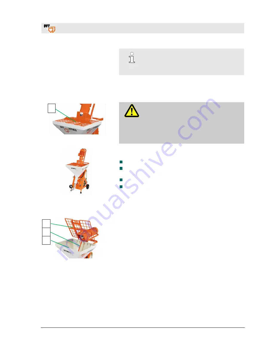
Fig. 31: Grille cover 


DANGER! 
Rotating mixing shaft! 

Risk of injury when reaching into the material 
hopper.  


During  machine  preparation  and  operation  the 
grille cover (1) must not be removed. 


Never reach into the running machine. 


Fig. 32: Set-up 

Put up the machine on a stable, even surface and secure against 
unwanted movements: 

  Neither tilt nor roll off the machine. 

  Put up the machine in such a way that it cannot be hit by falling 

objects.  

  The operating elements have to be freely accessible. 

  Maintain a clearance of approx. 1.5 metres around the 

machine. 


29.1 Open the protection grille 


Fig. 33: Open the protection grille 


1.  Loosen nuts (1) of the protection grille. 

2.  Tilt the protection grille with motor (2) backwards. 

3.  Remove the mixing shaft (3). 

4.  Close the protection grille with motor (2). 

5.  Firmly tighten the nuts (3) of the protection grille. 


Содержание 00 65 93 41

Страница 1: ...0 Operating manual Mixing pump RITMO L Eco Overview Operation Article number of the operating manual 00 62 15 20 Article number of the parts list machine RITMO L Eco 328 rpm 00 65 93 41 Read the opera...

Страница 2: ...l 2019 13 43 00 Knauf PFT GmbH Co KG P O Box no 60 97343 Iphofen Einersheimer Stra e 53 97346 Iphofen Germany Phone 49 9323 31 760 Fax 49 9323 31 770 Technical hotline 49 9323 31 1818 info pft net www...

Страница 3: ...th tilt flange 15 12 3 Chassis 15 13 Description of assemblies 16 13 1 Overview of frequency converter and on off switch 16 13 2 Overview of air compressor DT4 8 230 V 16 13 3 Overview of RITMO L Eco...

Страница 4: ...onnection cable of the gear motor 35 30 8 Open the protection grille 36 30 9 Close the protection grille with motor 36 31 Mortar pressure gauge 36 32 Hazardous dusts 37 33 Feeding dry material to the...

Страница 5: ...7 3 Cleaning the RITMO 55 47 4 Clean mortar hose 56 47 5 Remove the water hose 56 47 6 Cleaning the mixing tube 57 47 7 Insert the mixing tube cleaner 57 47 8 Clean the material container 57 47 9 Clea...

Страница 6: ...tdoor Directive 2000 14 EC Internal production control as per article 14 paragraph 2 in connection with annex V This declaration only refers to the machine in the state in which it has been placed on...

Страница 7: ...ects or if any other defects are detected that compromise a safe operation the supervisor has to be informed immediately In case of defects that cause harm to persons the operation of the construction...

Страница 8: ...has to be kept near the tool and easily accessible to the personnel at all times If the tool is given to third parties also include the operating manual The figures in this manual are for presentation...

Страница 9: ...information 12 April 2019 13 43 00 9 3 4 Spare parts lists Spare parts lists for the machine can be found on the Internet at www pft net Access to dealers with username and password Access 1 Homepage...

Страница 10: ...45 l 4 2 Electrical data of RITMO L Eco Electric 230V Detail Value Unit Voltage alternating current 50 Hz 230 V Power consumption max 9 5 A Power input max 2 2 kW Fuse protection 16 A Drive pump motor...

Страница 11: ...stretch 8 hours 4 5 Connection values of water Fig 1 Water connection Detail Value Unit Operating pressure max 2 5 bar Connection 1 2 inch 5 EMC test The machine has been subjected to an EMC test and...

Страница 12: ...owing details can be found on the name plate Manufacturer Type Year of manufacture Machine number Permissible operating pressure 10 Quality Control sticker Fig 4 Quality Control sticker The following...

Страница 13: ...ndle 2 Gear motor 3 Slider handle 4 Water flow meter 5 Water from water manifold to mixing tube 6 Needle valve water quantity 7 Wheel 8 Compressed air from air compressor to spraying gun 9 Water inlet...

Страница 14: ...manifold 5 Water flow meter water manifold 6 Frequency converter 12 Assembly units of RITMO 12 1 Mixing tube with material hopper Fig 7 Assembly unit of gear motor with material hopper The mixing pum...

Страница 15: ...verview Operation Assembly units of RITMO 12 April 2019 13 43 00 15 12 2 Gear motor with tilt flange Fig 8 Gear motor with protection grille Gear motor with protection grille and tilt flange 12 3 Chas...

Страница 16: ...frequency converter 6 Maintenance switch always at position ON Do not actuate maintenance switch 7 Selector switch of pump 8 Potentiometer for motor speed quantity of material 9 Push button green mach...

Страница 17: ...eter 3 Water flow meter 4 Floater water level indicator 5 Needle valve for water quantity 6 Solenoid valve 7 Pressure reducer 8 Pressure monitor of water pressure 9 Drain tap for frost protection 10 C...

Страница 18: ...15 1 Selector switch pump motor Fig 16 Operating modes pump motor The pump motor has three operating modes Selector switch position 0 The machine is switched off Selector switch right toggle The mach...

Страница 19: ...essories 12 April 2019 13 43 00 19 16 Accessories Fig 18 Water air hose 11 m art no 20211000 Fig 19 RONDO 25 mm 10 m hydraulic art no 00021100 Fig 20 Cleaner coupling 25 male part LW24 with Geka art n...

Страница 20: ...ressure 1 bar Maximum media and ambient temperature 75 C Assembly position as desired preferable horizontal 17 2 Intended use solenoid valve Scope of application Solenoid valves for liquid and gaseous...

Страница 21: ...or 18 1 Intended use air compressor The tool is conceptualised and designed exclusively for the purpose of use specified here Attention The air compressor is intended exclusively for the generation of...

Страница 22: ...mpressor complies with the national and international safety regulations and can therefore also be used in damp rooms and or outdoors Areas with clean and dry air should be preferred Ensure that the d...

Страница 23: ...nsured by means of water supply from a water reservoir by the PFT booster pump A flow pressure of at least 2 5 bar with the machine in operation on the construction side is guaranteed by means of suct...

Страница 24: ...hort as possible 21 Initial start up fill pump Fig 23 Fill pump Fill the PFT booster pump with water prior to initial start up to let the air escape from the pump housing Fill in water via water filli...

Страница 25: ...mp does not deliver after a short time this might be due to the following reasons There is still air in the pump and it has to be vented completely once again The suction line has a leak and the pump...

Страница 26: ...xing shafts PFT Material hoses should be used These are compatible with each other and form a constructive unit with the machine Non compliance does not only cause loss of guarantee but also bad morta...

Страница 27: ...bserve the symbols and instruction on the package Use only the specified anchorage points Remove packaging only shortly before the assembly Suspended loads WARNING Danger to life from suspended loads...

Страница 28: ...he delivery or under reserve only Note the extent of damage on the transport documentation or on the delivery note of the carrier Initiate complaint process NOTE Report any defect as soon as it is det...

Страница 29: ...at mortar pressure gauge 1 Carry out the following steps before beginning the transport 2 First unplug the mains cable 3 Unplug all other cable connections 4 Remove water supply line 5 Start transport...

Страница 30: ...r property Therefore Carry out all operating steps according to the instructions in this user manual Prior to starting your work ensure that all covers and protection devices are installed and work as...

Страница 31: ...tion the grille cover 1 must not be removed Never reach into the running machine Fig 32 Set up Put up the machine on a stable even surface and secure against unwanted movements Neither tilt nor roll o...

Страница 32: ...y converters 2 Pull the connector of air compressor 2 from the on off switch 29 3 Motor connection cable of pump motor Fig 35 Motor connection cable WARNING Danger to life from rotating parts Improper...

Страница 33: ...TE Never let the pump run dry as this reduces the service life of the pump 29 5 Connection of water from water tank Fig 38 Booster pump Fig 39 Suction strainer complete with filter screen Booster pump...

Страница 34: ...Water emerges from the mixing tube at the water hose 4 Adjust the expected amount of water at the needle valve 2 5 Evident on the floater 3 in the inspection glass of water flow meter 4 NOTE The spec...

Страница 35: ...mixing tube 30 6 Soaking of the mixing section 1 2 Fig 46 Soaking of the mixing section NOTE As a rule the pump has to be soaked The soaking makes it easier to start the pump 1 Turn the selector swit...

Страница 36: ...ille 4 Connect the motor connection cable to the gear motor Fig 50 Fit of the mixing shaft NOTE When inserting the mixing shaft 1 ensure that the mixing shaft engages with the head of the rotor 4 and...

Страница 37: ...ling the machine The rules of the Committee on Dangerous Substances AGS can be found under Technical Rules for Dangerous Substances TRGS 559 33 Feeding dry material to the machine Fig 53 Bagged goods...

Страница 38: ...he machine starts NOTE During daytime operation switch the machine on or off only at the selector switch 1 3 Adjust the potentiometer 2 for motor speed material quantity as required 4 Check material c...

Страница 39: ...mortar hose 1 at the mortar pressure gauge 2 NOTE Ensure clean and correct connection and tightness of the couplings Dirty couplings and rubber seals are not watertight and water might leak under pre...

Страница 40: ...ytime operation switch the machine on or off only at the selector switch 3 3 Adjust the potentiometer 4 for motor speed material quantity as required NOTE This small compressor may only be operated wi...

Страница 41: ...correct mortar consistency is reached if the material mixes on the surface to be sprayed we recommend application on wall surfaces from top to bottom If the water quantity is too little even mixing a...

Страница 42: ...emaining pressure can escape DANGER Danger of injury from discharged mortar Discharged mortar may lead to injuries to eyes and face Attention residual pressure 5 If the spraying gun is depressurised c...

Страница 43: ...lve 4 at the water manifold completely Fig 69 Pasty material 6 The pasty material can be filled in the material hopper 7 Turn the selector switch 5 clockwise to position FWD machine starts 8 Adjust th...

Страница 44: ...re are no persons in the danger zone anymore 9 Check the system before reactivation and ensure that all safety equipment is installed and functional 41 Measures to be taken in case of water outage NOT...

Страница 45: ...0 bar If required relieve the mortar pressure by slowly and slightly loosening the screws 2 In doing so cover the work area with film 3 Firmly tighten the screws 2 again 42 3 Restarting after power f...

Страница 46: ...or rectify the fault yourself NOTE The following fault table gives information on who is authorised to rectify the fault 43 2 Fault display of frequency converter Fig 74 Fault rectification The follow...

Страница 47: ...the device is disconnected and the intermediate circuit voltage is reduced This is not an error If the message appears during operation Check whether the supply voltage is too low 0 t Temperature of...

Страница 48: ...ch at the middle position Turn the selector switch clockwise Operator Machine does not start air Insufficient drop in pressure in the remote control due to blocked air duct or air nozzle pipe Clean bl...

Страница 49: ...tly or defective Adjust or replace air pressure safety switch Service engineer Air pressure hose defective or seals defective Replace air pressure hose replace seals or check compressor Service engine...

Страница 50: ...ce engineer Stator worn or clamp tightened too little Replace stator or re tighten clamp Service engineer Inner wall of mortar hose defective Replace mortar hose Operator Rotor too deep in pressure fl...

Страница 51: ...stallation start up and maintenance must be carried out by qualified personnel only 45 Transport is at a standstill Blockage Clogging might form in the conveying hoses for several reasons This means t...

Страница 52: ...al protective equipment protective goggles gloves for safety reasons and to position themselves in such a way that they cannot be hit by discharged material Other persons have to clear the area 46 1 L...

Страница 53: ...erefore Always wear protective goggles Always position yourself in such a way that you are not hit by the mortar being discharged 1 Cover coupling connections with tear proof film 2 Slightly loosen bo...

Страница 54: ...lector switch 1 to the 0 position middle position 7 Apply wallpaper paste to the cleaned mortar hoses and connect to the machine and spray gun 8 Insert the connector of air compressor into the blue so...

Страница 55: ...g machine parts they can open in an uncontrolled manner and injure the operator Open machine only when the pressure is at 0 bar NOTE Mortar hoses and spraying device have to be cleaned immediately aft...

Страница 56: ...n 5 Loosen the ring screw 6 and pull the air nozzle tube 7 out of the spray head 6 Open the tap Pos 2 Fig 83 until the sponge ball emerges from the spraying gun 7 In case of strong soiling repeat this...

Страница 57: ...ket housing must be closed with a protective cover 3 protection from moisture 47 7 Insert the mixing tube cleaner Fig 87 Insert the mixing tube cleaner 1 Insert cleaning shaft and mixing tube cleaner...

Страница 58: ...10 pin connector 3 8 Loosen the nuts 2 at the protection grille and tilt backwards 9 Take the mixing tube cleaner with cleaning shaft from the material hopper 47 10 Close the protection grille with mo...

Страница 59: ...easier pump replacement or to clean the pump RITMO can be laid on its back Fig 93 Remove pump unit 2 Loosen the screws 1 3 Remove and clean the pump unit 2 with mortar pressure gauge 4 Insert the cle...

Страница 60: ...inlet 2 Take the water hose 2 from the water nozzle in the rubber mixing section 3 Fig 95 Opening the drain tap 3 Open the drain taps 3 at the fitting block 4 Let the water drain and close the drain t...

Страница 61: ...Danger to life from electric current There is danger to life if you come in contact with live parts Activated electrical components can carry out uncontrolled movements and cause serious injuries The...

Страница 62: ...shortened according to the actual signs of wear Should you have any queries regarding maintenance works and intervals contact the manufacturer see page 2 for service addresses NOTE Maintenance is lim...

Страница 63: ...g of pressure reducing valve 1 4 bar at maximum flow Needle valve 1 completely turned 52 4 Check pressure switch 52 5 Pressure switch water Fig 101 Pressure switch If increased faults occur the water...

Страница 64: ...5 C 7 Store the compressor in a dry place and avoid condensation due to water vapour 8 Using the machine in an explosive atmosphere is forbidden High temperatures are generated on the compressor due t...

Страница 65: ...acement 52 8 Actions after completed maintenance 1 After finishing the maintenance works and prior to switching on the machine the following steps have to be carried out 2 Check all previously loosene...

Страница 66: ...Therefore Prior to starting the works ensure that there is sufficient space Carefully handle components with sharp edges Ensure order and cleanliness at the working place Loose components and tools o...

Страница 67: ...ssing materials and dispose of in an environment friendly way 54 Disposal If no agreement for the recovery or the disposal was made recycle the disassembled components Scrap metals Recycle plastic ele...

Страница 68: ...Mixing pump RITMO L Eco Overview Operation 68 12 April 2019 13 43 00...

Страница 69: ...se 39 Connect water draining cocks 34 Connecting the power supply 230 V 32 Connecting the spraying gun 40 Connecting the water supply 32 Connection of current 17 Connection of water from water tank 33...

Страница 70: ...ble of pump motor 32 N Name plate 12 O Open the air tap at the spraying gun 41 Open the protection grille 31 36 Operating conditions 11 Operating manual 8 Operating modes 18 Operation 30 Output values...

Страница 71: ...y 43 Storage 27 Structure of RITMO L Eco 13 Switch machine back on after blockage has been cleared 54 Switch on air compressor 40 Switching off RITMO L Eco 35 58 Switching on RITMO L Eco 33 Switching...

Страница 72: ...72 12 April 2019 13 43 00 The FLOW OF PRODUCTIVITY Knauf PFT GmbH Co KG P O Box no 60 97343 Iphofen Einersheimer Stra e 53 97346 Iphofen Germany Phone 49 9323 31 760 Fax 49 9323 31 770 Technical hotli...

Отзывы: