Product Description
2
01
7-
11
7
Connecting the Service Interface
1. First connect the round plug connector to the reader.
2. Connect the plug-in power supply to the parameterization cable.
3. Connect the plug-in power supply to a socket.
The ring light of the reader and the LED2 "PWR/ADJ/ERR/NO CODE" lights up
continuously or flashes.
4. Now connect the USB plug-in connector to your PC.
2.3
SSI Interface
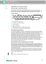
The controller and reader communicate via the SSI interface during operation. This is an
optically isolated RS422 interface. The controller sends a series of pulses via the clock+ and
clock- lines, and the reader responds synchronously with the 25-bit comprehensive response
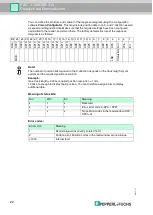
telegram. You can define the structure and content of the response telegram using the
Vision
Configurator
configuration software.
This may include position data in an X- and Y-direction as well as speed and diagnostic data.
During live operation, the reader is connected for communication via the SSI interface using
the "Main" connector.
2.4
LED Indicators and Controls
The reader has seven indicator LEDs for carrying out visual function checks and rapid
diagnosis.
Using the two control buttons on the rear of the device, you can activate the alignment aid and
the parameterization mode.
Button 1 is labeled "ADJUST." Button 2 is labeled "CONFIG."
COM
SSI D
A
T
A / CONFIG
OUT2 / ADJ
Y
OUT3 / ADJ Z
PWR / ADJ
ERR / NO CODE
INTERNAL
DIA
GNOS
TIC
ADJUST
CONFIG
1
2
LED 1 2 3 4 5 6 7


