Operation and Communication
2
01
7-
11
21
5
Operation and Communication
5.1
Communication via the SSI Interface
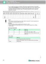
The reader has an SSI interface that enables it to read the current process data during
operation. This is an optically isolated RS422 interface. The controller sends a start sequence,
and the reader responds synchronously with the 25 bit comprehensive data telegram.
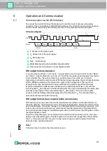
T: Duration of the pulse signal
T
p
: Pause time of the pulse signal
T
m
: Monoflop time
D24 ... D0: Data bits
MSB: Most important data bit (Most Significant Bit)
LSB: Least important data bit (Least Significant Bit)
SSI output format, standard
In an idle state, the
“
Data +
”
and
“
Clock +
”
signal cables are set to high (3.3 V) and the
“
Data -
”
and
“
Clock -
”
signal cables are set to low (-3.3 V). When the pulse signal changes from high to
low for the first time, the current status (e.g. position data, error codes, etc.) is stored
temporarily to initiate the data transfer. With the first rising pulse edge, the most important data
bit D
24
(MSB) is available at the serial data output on the reading head. The next most
important bit is then transferred with every additional rising pulse edge. When the least
important data bit D
0
(LSB) has been transferred, the data cable switches to low until the
monoflop time T
m
has elapsed. A further data transfer can only be initiated when the data cable
switches to high again or the pulse interval time T
p
has elapsed. At the end of the pulse
sequence, the last falling pulse edge triggers the monoflop time T
m
. The monoflop time T
m
determines the lowest transfer frequency.
SSI output format, dual request (slide valve mode)
With dual requests, the same data word is transferred several times via the SSI interface to
allow the detection of transmission errors. During multiple transfers, 25 bits are transferred for
each data telegram. If the pulse change is not interrupted after the last falling pulse edge, slide
valve mode is activated automatically, which means that the information stored temporarily
during the first pulse change is transmitted again. After the first transfer, the 26th pulse controls
the repeat transfer of data.
Therefore, if the 26th pulse occurs after a time shorter than the monoflop time T
m
, the same
data word is transmitted again. If the 26th pulse occurs after a time longer than the monoflop
time T
m
, this represents the 1st pulse in a new query sequence and the pulses that follow
transmit a new, updated data word.
SSI pulse diagram
Clock+
Data+
T
Tp
Tm
D24
D23
D22
D21
D2
D1
D0
LSB
MSB
Note!
If the clock line is inverted, the data word is moved.


