background image

PT495 Series Detector  

(Ultra1000)

   Rev 5.11 


16 

Operation 


Normal Operation 


The sensor is considered in normal operation after startup procedure is complete 

and is not indicating any alarm or sensor fail (FAULT) condition. 


Gas Reading Display 


The sensor displays the gas concentration in % volume or ppm (parts per million) 

by volume.    


Signal Output 4-20mA  


The 4-20mA signal output is directly proportional to the detection range of the 

sensor.  The output signal generated is proportional to the gas concentration 

displayed on the transmitter LCD. 

Use the formula below to compute the mA output for any given gas 

concentration or vice versa. 


Formula to convert gas reading to mA: 


   ( 16  x  gas_reading )     +  4    =  Analog output (mA) 


     Detection Range 


Formula to convert mA to gas reading: 


   ( mA Output  - 4  )      x   Detection Range   =  gas_reading 

           16 


(Note: Detection Range is the full scale range of the sensor) 


Содержание PT495 Series

Страница 1: ...ries Ultra1000 Stand Alone Addressable Gas Detector Toxic Oxygen Deficiency Combustible HC Revision 5 11 October 2020 Operator s Manual Pem Tech Inc Houston Texas U S A www pem tech com Gas Detection Technology ...

Страница 2: ...Reading Display 15 Signal Output 4 20mA 15 Calibration 18 Sensor calibration 18 Response check Bump Test 22 Adjusting or Re setting Zero Only 22 Calibration errors and remedies 23 Calibration Flow Chart 24 Edit Configuration alarms and Unit Address 25 Configuration menu 26 Set Detector Address 27 Set Alarm Levels 28 Alarm Conditions 30 Low Alarm High Alarm Fault 30 Resetting Alarms 31 Modbus RTU C...

Страница 3: ...e has to be performed then de classify the area before opening the sensor junction box The sintered flame arrestor on the stainless steel sensor head is an integral part of the complete sensor assembly Do not operate the gas sensor with the flame arrestor removed or damaged The detector muse be earthed grounded for the electrical safety A safety lug on the right side of the enclosure is provided f...

Страница 4: ...pecifications Height 7 4inches 188 mm Width 6 2 inches 159 mm Depth 4 9 inches 125 mm Display LC Display with backlight Status Indicators LC display for gas concentration Alarm status calibration mode and fault status Input Power 14 28 VDC 24 VDC nominal Power Consumption 55 mA 24 VDC typical Alarm Relays 3 each Fully programmable for Low High alarm levels and sensor Fault Also programmable as Lat...

Страница 5: ... lists the target gases and the detection ranges The unit displays the gas concentration and transmits a linear 4 20mA analog output signal proportional to the gas concentration displayed The unit is also equipped with 3 forms C type alarm relay contacts Two 2 alarm relays are fully programmable as Low and High alarms and 1 for sensor Fault or Malfunction The detector also features a non intrusive...

Страница 6: ...m 50 150 ppm 50 ppm 20 50 40 C 40 F 65 C 149 F intermittent 50 ppm 100 ppm Mercaptan 100 ppm 1 ppm 20 50 ppm 50 ppm 20 50 20 C 4 F 55 C 131 F 10 ppm 15 ppm Nitrogen Dioxide 50 ppm 1 ppm 10 50 ppm 10 ppm 50 75 20 C 4 F 55 C 131 F 10 ppm 15 ppm Nitric Oxide NO 100 ppm 1 ppm 20 50 ppm 25 ppm 45 60 20 C 4 F 55 C 131 F 20 ppm 50 ppm Oxygen O2 25 V V 0 1 Calibrated in fresh air Purged with Pure Nitrogen...

Страница 7: ...The termination or connection board consists of relays and DC DC power converters for the transmitter board and the sensor The power converters are protected against reverse polarity A 3 pin terminal is provided for user interface to the monitoring device for power input and 4 20ma output Three 3 Pin terminal blocks are also used for alarm connections Each pin on alarm terminal block is labeled as...

Страница 8: ...Dust guard To protect the sensor head assembly against the accumulation of dust sand on the sintered disk of the head assembly Also to protect against water splashes Duct Mount Kit This is an optional kit designed to monitor the gas vapors in Heating ventilation and air conditioning duct HVAC Figure 2 Transmitter and connection board assembly ...

Страница 9: ...nsor head assembly Calibration Adapter with Tubing Also a part of calibration accessories Used along with the flow regulator to flow the calibration gas to the sensor Attached is 6 feet nylon tubing Magnetic Wand A tool used to initiate the internal magnet sensitive switches for alarm configuration and to initiate sensor calibration Pipe Mount Assembly Includes hex bolts and stainless steel bracke...

Страница 10: ...cal pipe structure An optional pipe mount bracket can be used to mount the unit to a pipe up to 2 in diameter or cross section Two 2 Cable entries are provided on each side of the enclosure Either side can be used for the cable entry The other side must be plugged with the one supplied with the unit A CSA or ATEX approved plug must always be used 5 50 7 4 4 9 125mm 139 7mm 188mm Ø 0 3 7 6 mm 2 Pla...

Страница 11: ...If the serial communication port is to be used on the transmitter then connect RS485 terminal to the Communication Port of the PLC or the Control monitor using data quality type Shielded cable Two 2 core cable is used for Half Duplex RS485 data communication 4 For Audio Visual alarm connection or Alarm Relay Dry Contact refer to figure 5 for wiring diagram Be sure that the power rating of the alar...

Страница 12: ... 18AWG 21 4 6 5 670 2200 1 3 mm2 16AWG 13 4 4 08 1030 3400 2 0 mm2 14AWG 8 45 2 57 1490 4900 Data above is for a stranded copper type cable The max cable length is estimated based on 24 Volts DC power to the detector and maximum load of 100 Ω on the controller or signal receiver Max resistance per core R V I 8volts detector consumption A Max Loop resistance for toxic infrared 67 8 Ω Catalytic Bead...

Страница 13: ...PT495 Series Detector Ultra1000 Rev 5 11 13 Figure 4 Wiring Diagram for Power and 4 20 mA signal connection ...

Страница 14: ...PT495 Series Detector Ultra1000 Rev 5 11 14 Figure 5 Wiring diagram for Alarm Relay Connection ...

Страница 15: ...with the sequence as stated above then verify if the ribbon cable connector is plugged in properly If necessary unplug the ribbon cable and plug it back again The connector is keyed and can be inserted only one way The sensors are calibrated at the factory before they are shipped However it is a good practice to check the accuracy by simply applying the calibration gas after the warm up time and c...

Страница 16: ...al Output 4 20mA The 4 20mA signal output is directly proportional to the detection range of the sensor The output signal generated is proportional to the gas concentration displayed on the transmitter LCD Use the formula below to compute the mA output for any given gas concentration or vice versa Formula to convert gas reading to mA 16 x gas_reading 4 Analog output mA Detection Range Formula to c...

Страница 17: ...PT495 Series Detector Ultra1000 Rev 5 11 17 ppm Volume mA Output 0 4 0 10 5 6 20 7 2 25 8 0 50 12 0 75 16 0 100 20 0 The above table is for the detector with Full scale range of 100 ppm volume ...

Страница 18: ... Calibration gas bottle with flow regulator The flow of the calibration gas should be approximately 0 5 to 1 LPM liters per minute See Figure 7 for setup The sensor can be auto calibrated without removing the enclosure cover and declassifying the zone A magnet tool is used to activate the internal switch to initiate the calibration Once the calibration is initiated the alarm relays will be inhibit...

Страница 19: ...nts have been made remove the zero air if applied The unit will display the default Calibration Gas concentration or the concentration of the calibration gas used last time Make sure the Calib Gas value displayed on the LCD matches the gas concentration of the cylinder being used for calibration Else simply place and hold the magnet to the cover at 8 o clock position to change the default Calibrat...

Страница 20: ...ration data into memory When completed the display will starts flashing rapidly At this time remove the calibration gas and allow the sensor to clear Do not remove the calibration gas while the sensor is adjusting Remove the gas only when the adjustment is completed and the display is rapidly flashing with calibration gas value 10 After successful calibration Calibrat OK message is displayed for f...

Страница 21: ...f the sensor Target Gas Recommended Calibration gas Hydrogen Sulfide H2S Balanced in Air 50 ppm for 100 ppm range Sensor 20 ppm for 25 ppm range Sensor Carbon Monoxide 50 ppm CO balanced in Air Sulfur Dioxide 25 ppm SO2 Balanced in Air Ammonia 25 ppm Ammonia balanced in Air Oxygen Deficiency Pure Nitrogen Hydrogen 100 ppm Hydrogen balanced in Air Hydrogen Chloride 25 ppm HCL balanced in air Nitric...

Страница 22: ...place the magnet against the cover at 4 o clock position as shown in figure 8 4 Hold the magnet till the LCD displays Zero Adj OK Remove the magnet Sensor will return to normal operation Response Check Bump Test It is recommended to periodically carry out a gas response check or Bump Test on the detector to ensure proper operation 1 For a simple Bump Test apply the gas to the sensor via the tube f...

Страница 23: ...the voltage to be 5 volts 0 1 Time Out After initial adjustment the unit waits maximum of 60 seconds for the calibration gas Calibration is aborted if no calibration gas is detected by the microprocessor Check for the leaks in the calibration apparatus and check the flow rate Always use a calibration adapter and proper flow rate A completely dead sensor could also result in this error NO Gain At t...

Страница 24: ...y flashes calibration gas value at the slower rate when the gas is detected by the unit Apply Calib Gas for 1 2 minute Apply nitrogen for Oxygen sensor Display flashing once every second 1 2 minute calibration time ended Adjstng is displayed for few seconds Sensor making final adjustments and recording calibration data Do not remove the gas while ADJ is being displayed Remove Calib Gas when displa...

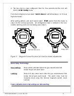
Страница 25: ...or will enter into Edit Config uration mode and the message is displayed on the LCD Remove the magnet The detector will scroll all the configuration options one at time Available options are shown below in configuration menu Edit all configuration parameters as necessary When completed select the Exit to return to normal operation Typically the configuration options are edited during installation ...

Страница 26: ...g the option edit the data value by holding the magnet to its place Remove magnet to end the data edit mode and return back to configuration options list Edit Config Set Address Set Low Alarm Set Hi Alarm Exit Set a unique address of the detector Address set between 1 and 120 Address 1 Low Alarm 10 Hi Alarm 15 Set Low alarm Level between 0 and full scale range Set to 0 to disable Low alarm relay S...

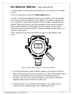
Страница 27: ...he data request from the master controller contains the sensor address The sensor with this unique address will respond to the request Follow the step by step instruction below to assign a unique address to the sensor 1 To modify the detector address hold the magnet to its position as shown in figure 9 The address will be incremented by 1 at a time Remove the magnet once the desired address value ...

Страница 28: ...isplay the current alarm level To change this current alarm setpoint continue to hold the magnet The alarm level is incremented by 1 Hold the magnet to its position until the desired alarm level is reached If the alarm value displayed is higher than the value desired simply hold the magnet to its position until the value rolls back to zero and then starts counting up again Or place the magnetic wa...

Страница 29: ...n volatile memory and is not lost during power down Alarm Relay Terminology Non Latching Relay will de activated when the gas concentration falls below the pre set alarm level Latching Relay will stay active even after the gas concentration falls below the preset alarm level The alarm relay must be manually reset using the internal magnetic switch next section Factory defaults alarm relay settings...

Страница 30: ...igh alarm condition if the gas concentration reaches the high alarm set point The high alarm relay is energized Fault Sensor Fail The transmitter is in Fault Malfunction condition when the sensor assembly malfunctions In Fault condition the 4 20mA output generated would be less than 1 0 mA The Display will show Sensor Fail Note Fault Alarm relay is normally energized This is to provide fail safe o...

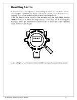
Страница 31: ...ly by using the magnetic wand as shown in figure 10 below Hold the magnet to its place for few seconds until the transmitter displays RESET on the LCD Move the magnet away The relays will be de energized however if the gas concentration continues to be above the alarm level the relays will be activated again Figure 10 Magnetic switch position 4 o clock to RESET alarms and to adjust alarm set point...

Страница 32: ...S Registers and Communication Sensor uses Modbus RTU as a standard protocol for communication between a PLC Controller and transmitter This section briefly explains the communication parameters for user PLC or controller to communicate with the transmitter Sensor acts as slave device to the master PLC controller The PLC communication port must be configured as follows Baud Rate 9600 Data Bits 8 Pa...

Страница 33: ...for sensor type and alarm status bits Each register is a 16 bit 2 byte register The value of the high order most significant byte of status register determines the type of sensor while each bit in the lower byte of the register determines a particular condition like active alarms or sensor malfunction The table below shows the high byte value of status register returned by the sensor and the corre...

Страница 34: ...brated The X in the bit position represents don t care or not defined condition Bit 7 Bit 0 X X X X X Fault Calibration Alarm Example Let say the value of the status register returned by the sensor is 257 decimal The value 257 means that the high order byte has the value 01 And low order byte has the value 01 The higher order byte 01 determines that it is an H2S sensor The low order byte when conv...

Страница 35: ...e sintered disk and reduce the diffusion of the gas into the sensor head assembly Sensor calibration schedule should be in place to ensure proper operation Protect sintered disk on the sensor head assembly from paint or high pressure water jets If necessary install some protective shield on the unit before painting or cleaning Be sure to remove the protective shield when finished Routine Maintenan...

Страница 36: ... necessary to turn off the power in order to replace the sensor head 3 Remove the junction box cover Unscrew 2 thumb screws on the transmitter board face plate and pull the board slowly Disconnect the ribbon cable and to remove the transmitter board assembly 4 Disconnect the sensor wires from the terminal block on the connection board 5 Unscrew the stainless steel sensor head to remove from the ju...

Страница 37: ...ected and let the sensor warm up as indicated in the Start up section in this manual 10 Calibrate the sensor Follow the instructions in calibration procedure in this manual Note Detector transmitter must be Calibrated any time a new sensor head assembly is installed or replaced ...

Страница 38: ... Sulfide H2S Range 25 ppm 61 495 100 25 S 384 Hydrogen Sulfide H2S Range 100 ppm 61 495 100 S 384 Hydrogen Sulfide H2S Range 500 ppm 61 495 100 5 S 460 Carbon Monoxide CO 61 495 102 S 138 Sulfur Dioxide SO2 61 495 103 S 130 Oxygen Deficiency O2 61 495 104 S 141 Hydrogen H2 Range 200 ppm 61 495 106 S 146 Hydrogen H2 Range 1000 ppm 61 495 106 1K S 824 Ammonia NH3 61 495 110 S 131 Nitric Oxide NO 61 ...

Страница 39: ...n Air 14 060 25 ppm SO2 Balanced in Air 14 100 25 ppm Ammonia balanced in Air 14 115 Pure Nitrogen for Oxygen 14 130 100 ppm Hydrogen balanced in Air For 200 ppm Range Sensor 14 085 500 ppm Hydrogen balanced in Air For 1000 ppm Range Sensor 14 087 50 ppm Nitric Oxide in Air 14 120 10 ppm Nitrogen Dioxide in Air 14 110 25 ppm Hydrogen Chloride in Air 14 125 5 ppm Chlorine in air 14 131 ...

Отзывы: