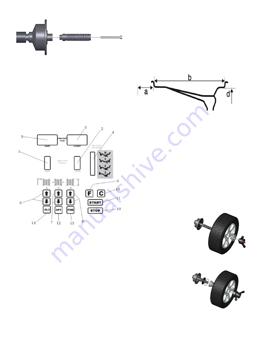
Mount the balance shaft on the drive shaft with
M10 x 150 bolt. Use a striking nutrunner (and a
long H8 hex bit socket). If the balance axis is loose,
there will be different measurement results.
The display is integrated with the machine.
NOTE! Use only your fingers to press the buttons.
Never use the counterweight pliers or other poin
-
ted objects.
Display and control panel
1. Indicator of the inside balance weight position.
2. Indicator for the outside balance weight
postion.
3. The display shows the outside correction
weight.
4. Indicator for the adhesive weight position in the
”ALU” position.
5. The display shows the inside correction weight.
6. Manual adjustment of the rim measured
distance (a).
7. Manual adjustment of the rim width (b).
8. Manual adjustment of the diameter (d) on the
rim.
9. Selection of static or dynamic correction.
10. Stop button.
11. Start button.
12. Optimization of imbalance.
13. Shows exact unbalanced weight.
14. Program selection for aluminum rims.
15. Recalculation of the balance sheet weight.
Combination functions for buttons
F + C .................................................. Self-calibration
F + FINE .............................................. Self-diagnosis
F + STOP .................... Adjusting the protectivehood
F + (a-) + (a +) .............Dimensions in inches or mm
STOP + C ........................... Reset to factory settings
Rim parameters
Assembly and disassembly of wheels
Before mounting the centering cone on the balance
shaft of the machine, check that the surfaces are
on the centering cone and balance shaft are clean,
no sand or dirt, and the tire is also clean. Remove
any previous balance weights, check air pressure
and that the rim is not damaged.
Then fit the appropriate centering cone.
Mount the wheel on the balance shaft and fasten
with the quick nut.
Remember that poor centering leads to
unnecessary imbalance.
Position of centering cone in most cases of
aluminum rims. (To protect the rim on the outside
against the quick nut).
Positive positioning is com
-
monly used. It works easily
and is useful for
different types of sheet me
-
tal rims and thin
aluminum rims. Placement
of centering cone in most
cases of sheet metal rims.
Negative positioning is
used to protect the inner
hole of the rim and the
main axle is positioned
exactly even if the outside
of the wheel is deformed.
Used for all sheet metal
rims, especially thick sheet
metal rims. rims, especially
thick sheet metal rims.
Disassembly of wheels
Release the quick nut by turning it
counterclockwise and then release it with the red
levers. Remove the cone and lift the wheel, being
careful not to scratch the balance shaft..
Содержание 506799
Страница 1: ...Automatic wheel balancer U 800 D ckbalanseringsmaskin U 800 Item No 506799...
Страница 12: ...Reservdelslista...
Страница 13: ......
Страница 14: ......
Страница 16: ...Funktionsdiagram...
Страница 17: ...Blockschema...
Страница 18: ......
Страница 29: ...Spare parts list...
Страница 30: ......
Страница 31: ......
Страница 33: ...Function diagram...
Страница 34: ......
Страница 35: ......
Страница 36: ...Verktygsboden Erfilux AB K llb cksrydsgatan 1 SE 507 42 Bor s Verktygsboden Bor s Sweden 0120504 03...


