

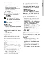
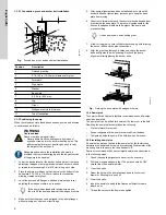
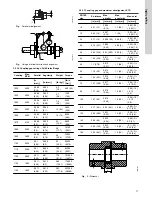
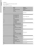


3.3.2.1 Foundation, grout and anchor bolt installation
1
2
3
4
5
6
7
8
11
9
10
TM054775
Fig.
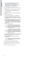
Foundation, grout, and anchor bolt installation
Position
Description
1
Finished grouting
2
0.75-1.25 in (19-32 mm) allowance for grout
3
Formwork
4
Pipe sleeve
5
Washer
6
Base plate
7
0.2-0.4 in (5-10 mm)
8
Lug
9
Grout
10
Wedges or shims left in place
11
Top of foundation
3.3.3 Positioning the pump
When the raised concrete foundation has been poured and allowed
to set, proceed as follows:
WARNING
Overhead load
Death or serious personal injury
‐
Never attempt to lift the entire pump by means of
eyebolts screwed into the driver mounting holes. This
attachment point may not be strong enough to carry
the weight of the entire unit.
Adequate space above the installation site must be
provided to accommodate rigging and the longest section
of the pump to be handled.
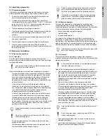
1.
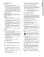
Lower the base plate over the anchor bolts and rest it on loose
adjustment wedges or shims placed near each anchor bolt and
at intervals not exceeding 24 in (610 mm) along each side.
2.
Place the shims or wedges so that they raise the bottom of the
base plate 0.75-1.25 in (19-32 mm) above the foundation,
allowing clearance for grout.
3.
Level the pump shaft, flanges, and base plate using a level,
adjusting the wedges or shims, as required.
If the pump is equipped with jacking screws, use
them to lift the pump and adjust the wedges or shims.
4.
Make sure that the pipes can be aligned to the pump flanges
without placing any strain on either flange.
5.
After pump alignment has been established, put nuts on the
anchor bolts and tighten them just enough to keep the base
plate from moving.
6.
Construct a formwork around the concrete foundation and pour
grout inside the base plate. The grout will compensate for the
uneven foundation, distribute the weight of the pump, and
prevent shifting.
Use an approved, non-shrinking grout.
7.
Allow for the grout to cure fully before proceeding with torquing
the anchor bolts and the pipe connections.
8.
After the grout has thoroughly hardened, check the anchor
bolts and tighten them if necessary. Recheck the pump
alignment after tightening the anchor bolts.
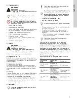
TM072276
Fig.
Raising the base plate with wedges or shims
3.3.4 Dowel pins
To comply with the Hydraulic Institute recommendations, all pumps
should be dowelled.
The pump feet can be drilled for dowels at the factory or in the field.
Doweling the pump feet accomplishes the following:
•
Prevents lateral movement.
•
Eases realignment if the pump is removed from the base.
•
Temporarily holds the pump if the hold-down bolts loosen.
3.3.5 Installing dowel pins
If dowel holes were not drilled in the pump feet at the factory then
determine the dowel and hole size by measuring the diameter of the
mounting hole in the pump foot and subtract 3/8".
Peerless recommends the use of straight dowel pins as described
in the following steps:
1.
Check the coupling alignment and correct if necessary.
2.
Drill holes in opposite pump feet. The holes should be 1/64"
smaller than the dowel diameter.
3.
Clear the debris.
4.
Ream the holes in the pump feet and base to the correct
diameter. Allowing for a push fit.
5.
Clear the debris.
6.
Insert the dowels to a depth that leaves sufficient thread to
attach a nut.
7.
Thread the nuts onto the dowel and tighten.
8
English (US)