


8.7 Inspecting the product
Before installation:
1.
Take inventory of the shipment to ensure that the received
parts match the list of parts on your order.
2.
Note the extent of damage or shortage on the freight bill and
bill of lading. Failure to note damage or missing parts may
result in declined warranty or refusing replacement of parts.
3.
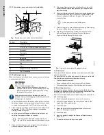
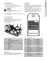
It is important that all the pump and system components are
identified and properly stored until installation, see
. There may be many small parts (such as line
shaft couplings or hardware) that are best left in their shipping
container until installation.
8.8 Repairing the product
Visually inspect parts for damage that affects serviceability or
sealing. Pay special attention to mating parts with relative motion,
for example, the wear rings.
Inspection
Perform a detailed inspection as follows:
•
Check O-rings and bearing cover gaskets for cracks, nicks, or
tears.
•
Check packing rings for excessive compression, fraying or
shredding, embedded particles (dirt or metal). Replace them if
they are defective in any way.
•
Mount the shaft between centers or on V-blocks. Check
for eccentricity throughout the entire length with a dial indicator.
Eccentricity must not exceed 0.003 in (0.08 mm) total
indicator reading.
•
Mount the shaft between centers or on V-blocks. Check
for eccentricity throughout the entire length with a dial indicator.
Eccentricity must not exceed 0.003 in (0.08 mm) total
indicator reading.
•
Examine the volute for cracks, dents, gouges or embedded
material.
Repairs
Make needed repairs in the following manner:
•
If the inner diameter (ID) of casing rings (7) is grooved, scored
or eccentric, replace the casing rings.
•
If the impeller wear surfaces or impeller rings (8) are defective,
the impeller must be machined to install new impeller rings. Be
sure machining is concentric with the impeller bore. Use care
NOT to reduce hub outer diameter (OD) when machining off
old impeller rings.
•
Install new impeller rings (8) on the impeller (shrink or press
depending on the material).
•
Replace worn shaft sleeves.
•
Replace shafts having excessive run-out (eccentricity).
8.9 Assembling the pump
Take care not to damage any components and avoid
contamination (dirt, debris, moisture, etc.) of the unit.
Peerless does not recommend reusing gaskets, O-rings,
packing rings, or ball bearings.
1.
Support the pump shaft in blocks and rails to protect it
from bending or being damaged during the re-assembly
process.
2.
Check that the shaft is straight and free of nicks and scratches.
Remove all burrs and scratches with a fine file.
3.
Coat the shaft (6) lightly with oil.
4.
Place impeller key (32) in shaft keyway.
5.
Align impeller (2) on the shaft and install with an arbor press
or brass tubular sleeve and hammer. When assembled,
the impeller vanes must rotate in the proper direction.
6.
Impeller hub must be centered on shaft journal.
7.
Apply a thread locker on the shaft sleeve, set screws and
install them in the shaft sleeves. Assemble shaft sleeves to the
shaft and hand tighten against the impeller. Tighten the set
screws to a minimum torque of 12 ft-lbs.
We recommend using Loctite 242 thread locker.
Apply a 360° bead of thread locker to the first few
threads, leaving the first thread-free.
8.
Install the stuffing box bushings (63).
9.
Locate casing rings (7) on the impeller.
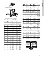
10. If casing and or impeller wear rings are required, fit wear
rings into the casing or onto the impeller skirt. Contact Peerless
if rings should be pressed or secured to part as needed. The
final clearance of rings should provide the clearance shown
in the table in section
. If clearance is
not achieved, machine rings before proceeding.
11. Insert board deflectors (40A) on the shaft.
12. If previously removed, install bearing housing seals (169)
into housings (31 and 33).
13. Press housing-bearing-seal assemblies on the shaft to
seat bearings against shaft shoulder fillet.
14. Install bearing retaining ring (18A) in the groove against the
outboard bearing.
15. Install gaskets (73B) on bearing covers. Use factory
supplied parts or cut replacement gaskets from 0.06 in (1.52
mm) No. 444 Vellumoid. (SAEP3415A). EXCEPTION: For all
models using 3306 size outboard bearing, gasket 73B is 0.03
in (0.8 mm).
16. Install outboard deflector (40B) and coupling key (46).
17. Affix the new casing gasket (73A) to the lower casing (1A) with
lubricant.
It is very important that the specified material and
thickness are used for casing gasket. Machined
surfaces of both casings must be perfectly clean and
free from burrs or nicks.
18. For the 12AEF21, follow step a before step b, for all other
models follow step b only:
a. If the bearings bracket has been removed, install it before
setting the rotating element into the lower casing.
b. Use slings around the shaft near the bearings to set the
rotating element into the lower casing.
19. Position the casing rings (7) and both bearing housings so that
all dowel pins engage in slots in the lower case split surface.
20. Assemble both bearing caps per match marks, and tighten
the cap screws.
21. Adjust the shaft sleeves (14 and 14A) to center the impeller
in the lower casing, and tighten both shaft sleeves with
a spanner wrench, then add Locktite to the shaft sleeve
set screws. Then tighten shaft sleeve set screws according
to section
.
22. Cover the top side of the casing gasket with a lubricant.
23. Install the gland bolts (17B). Carefully locate the upper
casing on the lower casing, making certain the dowel pins
engage.
21
English (US)