


22. Remove housings (31 & 33), bearings (16 & 18), and bearing
housing seals (169).
Use a bearing puller.
23. Remove the deflectors (40A).
24. Remove the casing rings (7).
25. Remove the packing rings (13), lantern rings (29), and stuffing
box bushings (63).
Lantern rings may not be present.
26. For the 12AEF21, follow step a, and for all other models follow
step b.
a. Loosen the shaft sleeve set screws and remove the shaft
sleeves and shaft sleeve nuts.
b. Loosen the shaft sleeve set screws and then the shaft
sleeves (14 & 14A).
Use a spanner wrench to remove the shaft
sleeves. Sleeve (14) has a right-hand thread, and
sleeve (14A) has a left-hand thread.
27. Remove the sleeves (14 & 14A) from the shaft.
Do not damage the O-ring (14B) between the shaft
and the sleeve.
28. Remove the impeller (2) from the shaft.
Use an arbor press. The tolerance for the fit between
the impeller hub inner diameter and shaft outer
diameter is within the ANSI B4.1 [LC] standard.
29. Remove the impeller key (32).
30. Clean all parts:
a.
Do not clean the bearings. Do not use a metal or
wire brush.
Clean metal parts with a solvent.
Use a bristle brush.
b. Scrape gasket and lubricant from flanges.
31. Replace or recondition worn or defective parts if the following is
observed:
a. O-rings and bearing cover gaskets have cracks, nicks, or
tears.
b. Packing rings are excessively compressed, fraying or
shredding, or embedded with particles (dirt or metal).
c. Check the entire shaft length for eccentricity with a dial
indicator. Runout must not exceed 0.003 in (0.08 mm).
Mount the shaft between centers or V-blocks on a
level surface.
d. Check that threads are clean and sharp.
e. Check bearing surfaces for smoothness, and verify that the
finish is within 32 µin (0.81 µm) or less.
f. Verify that the shaft shoulders are square and free from
nicks.
g. Examine passages for cracks, dents, gouges, or embedded
material.
8.3.1 Accessories
Please see the manuals supplied with the accessories.
8.4 Wear ring
Wear rings decrease the clearance between the impeller and volute
to reduce the quantity of liquid leaking from the high-pressure zone,
outlet, and the low-pressure zone, inlet. The rings are designed to
use the pumped liquid for lubrication and to be replaced when worn
to maintain optimal pump performance and service.
As the rings wear, the clearance between the impeller and
the volute increases as does the amount of liquid leaking from the
high-pressure to the low-pressure zone. The rate of wear depends
on the characteristics of the pumped liquid. The pump will typically
have a volute wear ring and can also have an impeller wear ring.
Badly worn wear rings will result in severe degradation of pump
performance: head and flow rate, especially on small
pumps. Examination of wear patterns can provide valuable
information to diagnose pump performance or maintenance issues
and determining the source of a problem.
8.5 Replacing the wear ring
Standard pumps are not supplied with impeller wear rings, and they
can be installed in the field. The wear surface of the impeller is an
integral part of the impeller. Impellers with worn surfaces that
cannot be fitted with wear rings must be replaced.
Use the following steps to determine if the wear rings must be
replaced:
1.
Measure the outer diameter (OD) of the impeller wear surface
or wear ring (8) and the inner diameter (ID) of the volute wear
ring (7).
2.
Compute the diametrical clearance, ID minus OD, and
compare them with the allowed diametrical clearance.
3.
If the measured clearance is out of tolerance, proceed as
follows:
Ensure the ID of the volute ring is concentric with the
wear ring OD, and the surface is smooth.
a. Replace the volute wear ring and impeller wear ring if the
measured clearance is two times the maximum allowed
clearance.
Machining the impeller wear surface may be
necessary to install or replace the impeller wear
rings. Ensure that the impeller OD is not reduced
and is concentric with the bore of the impeller.
Bronze impeller rings are shrink-fitted onto the hub
according to ANSI B4.1 [FN-4].
Hardened impeller rings are installed according to
ANSI B4.1 [FN-1].
b. Replace the volute wear ring if the measured clearance is
out of tolerance.
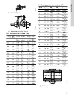
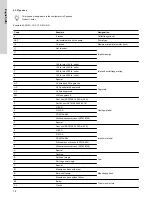
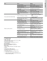
8.6 Diametrical clearance
Clearances are for the standard bronze or cast iron fitted
pumps. For materials with a tendency to gall such as
stainless steel, increase clearances by 0.01 in (0.25 mm).
Pump size
Diametrical clearance [in
(mm)]
Typical
0.015 to 0.019 (0.381 to 0.48)
10AEF16, 10AEF20
0.018 to 0.022 (0.457 to 0.559)
6AEF17
0.025 to 0.029 (0.635 to 0.737)
20
English (US)