

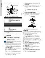


3.5.3.4 Aligning the engine drivers
Engine-driven units are typically supplied with the pump and drive
on a common base plate. For units that are supplied separately,
contact Peerless.
If a universal drive is installed, contact the manufacturer
for instructions.
1.
Check the angular alignment between the pump and engine
shafts.
2.
Check the parallel alignment between the pump and engine
shafts.
3.
When coupled, verify that the angle between the pump and
drive shaft is less than three degrees. For assistance,
contact Peerless.
4.
Verify that at least 3/4 of the key is engaged with the coupler
and shaft.
3.5.4 Lubrication, priming and cooling systems
If supplied, please refer to additional documents attached to the
pump, or contact Peerless.
3.6 Electrical connection
All electrical connections must be carried out by a
qualified electrician in accordance with local regulations.
DANGER
Electric shock
Death or serious personal injury
‐
Switch off the power supply before you start any work
on the product.
‐
Make sure that the power supply cannot be switched
on accidentally.
Locate the electrical conduit and boxes so as to avoid obstruction of
the pump.
Check speed versus torque requirements during the starting phase
of a pump against the speed versus torque curve of the driving
motor.
In order to accelerate the pump up to rated speed, the driver should
be capable of supplying more torque at each speed than required
by the pump. In general, this condition is easily attainable with
standard induction or synchronous motors, except under certain
conditions when a motor with high pull-in torque may be required,
such as high specific speed pumps over 5000 US units (100 metric
units) or reduced voltage startup.
To achieve a smooth start for the pumping equipment, consider
connecting autotransformers to the starting panel or using solid-
state starters. These provide a gradual increase in voltage up to
rated voltage ensuring even acceleration.
Control, monitoring and alarm equipment
All control and alarm systems should be checked for
correct installation and functioning in accordance with the
manufacturer's instructions. All alarm point settings should be
checked.
Stopping the unit/reverse runaway speed
A sudden power and/or discharge valve failure during
pump operation against a static head will result in a flow reversal,
and the pump will operate as a hydraulic turbine in a
direction opposite to that of a normal pump operation. If the driver
offers little resistance while running backward, the rotational speed
may approach the pump specific speed. This condition is called
runaway speed and causes mechanical problems. Contact Peerless
for aid in preventing this condition.
3.7 Control, monitoring, and alarm equipment
Check control and alarm systems for correct installation
and function according to the manufacturer's instructions.
Check all alarm point settings.
3.7.1 Stopping the unit/reverse runaway speed
A sudden power and/or discharge valve failure during pump
operation against a static head will result in a flow reversal, and the
pump will operate as a hydraulic turbine in a direction opposite to
that of a normal pump operation.
If the driver offers little resistance while running backward, the
rotational speed may approach the pump specific speed.
4. Preparing the pump for startup
4.1 Lubricating the pump
Before attempting to start the pump, check the following items:
•
lubrication fitting at packing, if applicable
•
lubrication for pump bearing
•
lubrication of the driver
•
oil-cooling connections for the driver, if applicable
•
coupling, refer to the manufacturer's instructions.
Good practice includes the following:
•
Keep lubricant clean, and use a dust-tight cover on the storage
container.
•
Use the oldest lubricant first.
•
Clean the pump lubricant fittings before re-lubricating with
grease.
•
Use clean dispensing equipment.
•
Remove 0.25 in (6.4 mm) of drain pipe plug on the bottom
outside of the bearing housing cover. Inject clean, new grease
forcing out the old grease through the drain opening.
•
Start and run the pump for a short time to eject any excess
grease. Reinstall 0.25 in (6.4 mm) of pipe plug. Wipe off any
ejected grease.
•
Use the proper amount of lubricant. Too much lubricant results
in churning, unnecessary power consumption, rapid heating to
a high temperature and inadequate lubrication.
Normal bearing temperatures vary with the seasons and
environment and may range from 0 to 250 °F (-18 to 121
°C). A continuous rise from the established, normal
operating temperature indicates trouble and probable
failure of the bearing. Shut down the pump immediately.
12
English (US)