

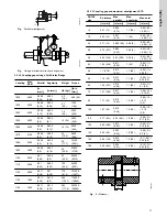


Pressure gauges will enable the operator to monitor the
pump performance and determine whether the pump
conforms to the parameters of the performance curve
If cavitation, vapor binding, or other unstable operating
situations occur, the pressure gauges will indicate with
wide fluctuation in the inlet and outlet pressures.
3.5.1.4 Outlet pipe
•
A short outlet pipe can be the same diameter as the pump
outlet port. A long outlet pipe must be one or two sizes larger
than the outlet port, depending on the length.
•
It is best to use long horizontal outlet pipes.
•
Install a non-return valve to protect the pump from backflow
and excessive backpressure. The check valve should be
installed between the isolation valve and pump.
Pump backspin and hydraulic shock can cause severe
damage to the pump and driver.
•
Install a gate valve near the outlet port to be able to isolate the
pump during shutdown and maintenance, and to facilitate
pump removal.
•
Any high points in the outlet pipe may entrap air or gas and
thus reduce pump operation.
Operating pumps against a closed valve will cause an
increase in pressure and power.
If an increaser is used on the outlet pipe to increase the
pipe size then it should be placed between the non-return
valve and the pump. If expansion joints are used then
they should be placed between the pipe support or anchor
and the non-return valve.
3.5.1.5 Nozzle load
The pipes should be aligned with the pump nozzles to minimize
pump nozzle loads. Refer to ANSI/HI 9.6.2 for assessment of
applied nozzle loads.
3.5.2 Impeller clearance
To achieve optimal performance and service life, the impeller
clearance must be centered in the volute. Pumps are shipped from
the factory with the impeller clearance set.
3.5.3 Alignment
Misalignment of the pump and driver can cause product
failure.
Reliable, trouble-free, and efficient operation requires accurate
alignment of pumps and drivers mounted on a common base plate.
Shipping and installation can alter the factory alignment. Therefore,
check the alignment after:
•
mounting.
•
the grout has hardened.
•
the foundation bolts are tightened or adjusted.
•
the pipes to the product are connected.
•
pump, driver or base plate is moved.
To check alignment, mount a dial indicator to measure shaft
movement before and after tightening the flange bolts.
To facilitate accurate field alignment, we do not dowel the
pumps or drivers on the base plates before shipment.
If the product does not stay in alignment after installation, possible
causes of misalignment are:
•
setting, seasoning or springing of the foundation.
•
excessive force on the pipes distorting or shifting the machine.
•
settling of the building.
•
shifting of pump or driver on the base plate or foundation.
Misalignment may be the cause of:
•
noisy pump operation
•
vibration
•
premature bearing failure
•
excessive coupling wear.
3.5.3.1 Checking the alignment
The procedure for verifying the alignment of a pump and driver
connected by a flexible coupling, mounted on a common base plate
are:
1.
Disconnect the coupling halves.
2.
Set the coupling gap to the recommended alignment
dimension.
3.
Test for parallel and angular alignment with a straight edge and
feeler gauge.
4.
An alternate test for parallel and angular alignment may
be made as follows with a dial indicator mounted:
• Scribe the index lines on the coupling halves or set the
indicator dial to zero.
• Slowly turn both coupling halves so that the index lines
match.
• Observe the dial reading to determine whether pump or
driver
• Acceptable parallel and angular alignment occur when total
indicator reading (complete turn) does not exceed limits
shown on either a tag or decal on the unit or on the unit
outline drawing.
5.
When a significant operating temperature differential exists
between the pump and driver (i.e. a steam turbine driver
with a pump handling cold liquid), thermal growth causes the
hotter component to rise. You can compensate for this by
initially setting the hotter unit 0.003 to 0.005 in. (0.076 to 0.127
mm) lower. When both units are at normal operating
temperature, make a final check and correct the alignment if
necessary.
Check for correct electric motor rotation while
coupling halves are disconnected.
6.
Correct for excessive parallel and angular misalignment by
slightly shifting the leveling wedges under the base plate. Tap
lightly (in or out) with a hammer. Retest alignment each time
after you shift a wedge.
7.
It may be necessary to change the shims under the pump or
driver or even relocate the pump or driver on the base plate.
Make such changes only after you are sure that shifting the
wedges do not achieve alignment.
8.
If wedges are shifted or shims are shifted, recheck the pipe
alignment and the level of the shafts.
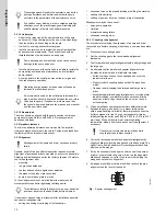
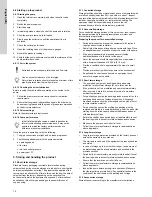
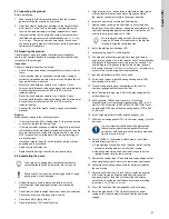
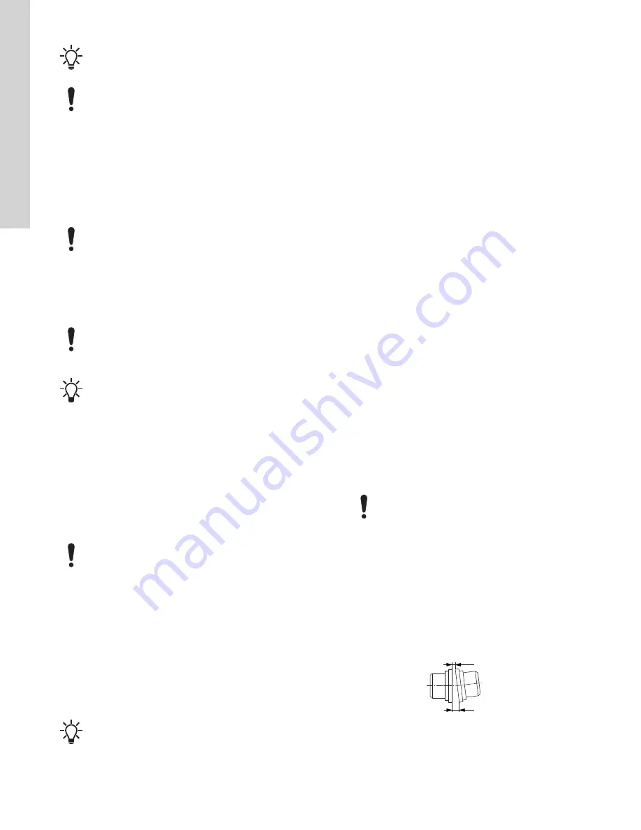
X
Y
TM060221
Fig.
Angular misalignment
10
English (US)