Better Solutions Are Within Reach
TM
MODEL NUMBER:
PDI-P26/ P32/ P40 LCD
Document Number:
PD196-145R3
Quick Start Guide
Page 3 of 9
PDi Communication Systems, Inc. 40 Greenwood Lane Springboro, Ohio 45066 USA PH 1-800-628-9870 FX 937-743-5664
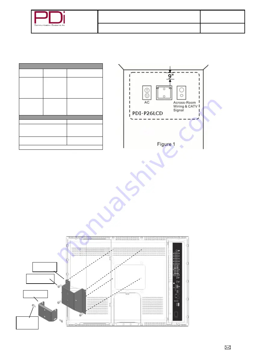
Wall MOUNTING STANDARD WALL BRACKET for PDI-P26LCD TV
The PDI-P26LCD TV
is mounted to the wall with a PD168-103 mount
(Not supplied with TV)
or a PD168-203 mount
(Not supplied with TV)
. The
PD168-203 mount is a heavy duty mount and is to be used if a DVD or an IPT module is going to be mounted on the P26. A PD168-203 wall mount
connects to a PD181-674 LCD mount. A PD168-103 wall mount connects to a PD181-597 LCD mount.
Mounting Connections
Figure 2
M4 x 6mm
Screws
Pilfer
Screws
LCD mount
Wall Mount
Attach with the four M4 screws (PDIPPHMSM4X76) that
are provided.
4. Mate the LCD mount to the wall mount, making sure the
pivot pins are retained in the slots.
5. Secure with two 10x32 Pilfer screws
(PDIPPBHSCS103250).
6. The TV’s tilt can be adjusted by loosening both Pilfer
screws, adjusting tilt, and then tightening the screws.
Mounting Pieces
Wall
Mount
LCD
Mount
Purpose
PD168-103
PD181-597
For mounting PDI-
P26LCD TV to wall
without
DVD
and/or IPT
Modules (1)
PD168-203
PD181-674
For mounting PDI-
P26LCD TV to wall
with
DVD and/or
IPT Modules (1)
Screws
Part #
Part
PDIPPBHSCS103250
10-32 X ½ Pilfer
Proof PIH Button
Head (2)
PDIPPHMSM4X76
M4-.7 X 6MM
PPHMS (4)
Numbers in parenthesis represent quantity
1.
Refer to Figure 1.
Select a location on the wall
approximately 9 inches below the ceiling.
NOTE
:
DO NOT locate AC, Across-Room
Wiring, and CATV Signal outlets below the
Wall Bracket’s location as it will cause
clearance issues and interfere with the TV’s
cabinet when mounted to the bracket.
2. Position the wall mount and locate the two
mounting holes. Secure the bracket to the wall
(mounting hardware is not included).
3.
Refer to Figure 2
. Position the LCD mount on
the LCD TV cabinet.


