background image


MODEL:


PDi BELLA-HD Interface


Document Number:


PD196-426R1 


User Manual 

Page 13 of 27 


PDi Communication Systems, Inc. ▪ 40 Greenwood Ln ▪ Springboro, Ohio 45066 USA ▪ 

www.PDiarm.com

 and 

www.mymedTV.com

 ▪ Phone 800.628.9870 


TV Setup – A-Series 

To establish communication to interface module the CCI port on the TV must be active and you must have a PDi programming remote 
PD108-420 (not included).   
 

1.


From the TV, open the TV Setup Menu by pressing SETUP on the programming remote.  

2.


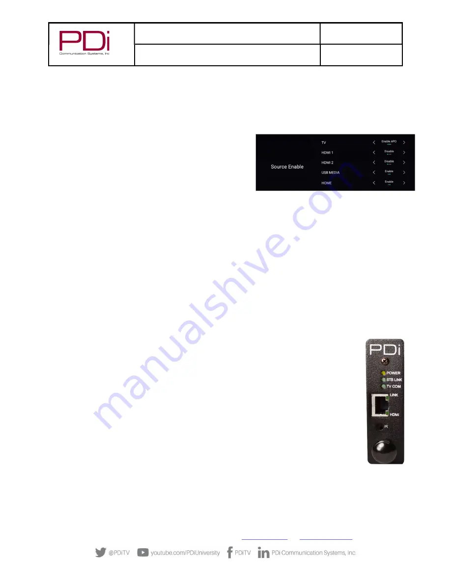
Select “Sources” and then select “Source Enable”.  Set each item as detailed below. 

The TV Source Setup must properly reflect the actual connections 
to the TV.  Incorrect settings will result in loss of programming or 
the addition of blank signal sources.  In most installations, both 
cable/satellite and off-air programming is delivered over RF so 
the “TV” must be enabled.  If the cable/satellite channels are 
delivered over an alternate method such as HDMI, then that 
source must be enabled.  All unused sources should be disabled.   

TV Setup – medTAB 

medTAB14C, medTAB19C, and medTAB16C are compatible with PDi interface modules. To establish communication to interface 
module the CCI port on the TV must be active.  Setup on the medTAB14C and medTAB16C can be completed with a PDi programming 
remote PD108-420 (not included).  medTAB19C setup is completed through onscreen touchscreen controls.   
 

1.


From the TV app, open the TV Settings Menu, by pressing SETUP on the programming remote or by pressing Settings on the 
touchscreen TV controls.  Enter password (“45066” is factory default).  

2.


Select “Advanced Option”. 

3.


Select “Features” then select “Input Sources”.  Set each item as detailed below. 
 
The TV Source Setup must properly reflect the actual connections to the TV.  Incorrect settings will result in loss of 
programming or the addition of blank signal sources.  In most installations, both cable/satellite and off-air programming is 
delivered over RF so the “TV” must be enabled.  If the cable/satellite channels are delivered over an alternate method such as 
HDMI, then that source must be enabled.  All unused sources should be disabled.   
 

Verifying and Troubleshooting Connections 

The following steps verify the data connections between the STB and TV.  These instructions assume you have 
followed the previous connection and TV setup sections of this manual. 
 
1.


Power the TV. 

2.


Power the set-top-box.  

3.


Power the interface module.  Note-If using a DirectTV box, power is through the USB cable. 

4.


Examine the front mounted status lights on the PD295-004 interface module.  It contains a POWER, STB (set-
top-box), TV COM, LINK, and HDMI status lights.   

a.


Each light will turn green (yellow for power) when properly connected. 

b.


A dark (Off) status light indicates a problem.   

c.


A blinking STB LINK LED indicates data transfer.  HDMI blinking means HDMI video content is not 
copy protected. 

d.


All 5 lights lit indicate all connections are working properly and HDMI is being sent to the TV. 

 
Please review the “Troubleshooting” section for additional help. 
 
NOTE:  While the LINK light indicates a working connection to the TV, it does not confirm the audio/video (RF or 
HDMI) from the STB is connected to the correct TV.  


Содержание BELLA-HD PD295-004

Страница 1: ...USER MANUAL Document Number PD196 426R1 mymedTV com PD295 004 BELLA HD Set Top Box Interface Module...

Страница 2: ...Vs 12 TV Setup A Series 13 TV Setup medTAB 13 Verifying and Troubleshooting Connections 13 Power 14 STB Link 14 TV COM 14 LINK 14 HDMI 14 Interface Module Setup Menus 15 Accessing Interface Module Set...

Страница 3: ...ing instructions do not attempt to service it yourself as opening or removing covers may expose you to dangerous voltage or other hazards Refer all servicing to qualified service personnel Damage Requ...

Страница 4: ...s convenience receptacles and the point where they exit from the apparatus 11 Only use attachments accessories specified by the manufacturer 12 Use only with the cart stand tripod bracket or table spe...

Страница 5: ...ate signals for distribution by sending HDMI from each set top box directly to an associated TV It offers customizable key mapping and works in many retrofit installations Best of all it s made in Ame...

Страница 6: ...nects to the TV via standard CAT6a cable CAT6a provides a higher bandwidth needed for the HDMI video signal and the length should not exceed 250 feet BELLA must be powered via the rack mounted chassis...

Страница 7: ...L PDi BELLA HD Interface Document Number PD196 426R1 User Manual Page 7 of 27 PDi Communication Systems Inc 40 Greenwood Ln Springboro Ohio 45066 USA www PDiarm com and www mymedTV com Phone 800 628 9...

Страница 8: ...ems or your PDi distributor for assistance should your TV and or Arm lack this cable Arm Mounted TV Data Power and IR Emitter Cable Installation The CAT6a cable used to connect the remotely located TV...

Страница 9: ...dual or central style The individual power supply mounts near the TV injecting power from a nearby AC outlet onto the incoming coaxial cable The central supply injects power onto 10 separate coax cabl...

Страница 10: ...he need for the power passers NOTE The PD167 003 Power Passer is an optional device NOT supplied with the interface module and is only required for centrally powered arm mounted televisions Please con...

Страница 11: ...loss and high isolation 1 Remove power from the TV at the central power supply 2 Connect a coaxial cable from the set top box OUT TO TV to one of the 10 RF IN ports on the PDI 772HE IND 3 Connect the...

Страница 12: ...Other TV s may operate the interface module on any Standby Power setting This can be determined by trying it or contacting PDi 4 From the initial setup menu select Channels 5 Change the Pro idiom opt...

Страница 13: ...he touchscreen TV controls Enter password 45066 is factory default 2 Select Advanced Option 3 Select Features then select Input Sources Set each item as detailed below The TV Source Setup must properl...

Страница 14: ...good between the minimod and the TV but not necessarily communication to the TV board See the TV COMM description above Off No CAT6 connection to the TV If this light is off and the POWER light is on...

Страница 15: ...VOL on the remote to cycle through a menu item s setting options 6 When finished press SETUP to exit the interface module setup menu and save changes Accessing Interface Module Setup Menus on medTAB C...

Страница 16: ...INTERFACE MODULE SETUP TV KEY STB COMMAND 0 Digit 0 1 Digit 1 2 Digit 2 3 Digit 3 4 Digit 4 5 Digit 5 6 Digit 6 7 Digit 7 8 Digit 8 9 Digit 9 Dash Info Return SETUP OK LAST INTERFACE MODULE SETUP TV K...

Страница 17: ...e the STB Model selection The default settings for each supported STB are detailed below in Appendix B STB Functions and Default Mapping Reference Flash Intface Pwr LED This provides a diagnostic tool...

Страница 18: ...ble Spectrum Spectrum101 T SciAtl Cisco Verizon Moto Arris Keypad Programming Mapping Instructions The set top box STB can be controlled remotely by any of the following that incorporate a keypad Pill...

Страница 19: ...Remote TV AV An Example for Off Air RF Pass Thru A facility has an outside antenna that contains several local TV channels that they wish to provide to their patients for viewing in addition to Satell...

Страница 20: ...t will not match the settings that came preloaded onto the Interface 1 Enter the Interface Module Setup Menu See Understanding Interface Module Setup Menus earlier in this manual 2 Select menu Interfa...

Страница 21: ...the same area The IR emitter supplied with the PD295 004 allows the pass through of other external IR signals through its outward facing side This IR emitter also sends the IR signal out the side oppo...

Страница 22: ...rameter is set to the source input such as TUNER HDMI 1 etc that matches the set top box s connection to the TV See Programming the STB Signal Input Type page 20 c If the video input to the TV is RF T...

Страница 23: ...TV Setup and Understanding Interface Module Setup Menus for programming details NOTE A Control Device Key also referenced as a TV Key is a key located on the front panel of a PDi TV and or on a PDi TV...

Страница 24: ...Digit 9 Digit 9 Power Power Power Power Power Power Power Power Info Info Info Info Info Info Info Info CH CH CH Up CH Up CH Up CH CH CH CH CH CH Down CH Down CH Down CH CH CH OK Select OK Select Sele...

Страница 25: ...3 Digit 3 Digit 3 Digit 3 Digit 3 4 Digit 4 Digit 4 Digit 4 Digit 4 Digit 4 Digit 4 Digit 4 Digit 4 5 Digit 5 Digit 5 Digit 5 Digit 5 Digit 5 Digit 5 Digit 5 Digit 5 6 Digit 6 Digit 6 Digit 6 Digit 6...

Страница 26: ...ow Right Arrow Right Arrow Dash Info Info TV FM Exit Exit Exit Cancel Exit Cancel Clear Clear Exit TV AV Input SAP MTS Language D Language D Audio Ch List Guide Guide Guide Guide Guide Guide Guide Gui...

Страница 27: ...ymedTV com Phone 800 628 9870 Limited Warranty PDi Communication Systems Inc PDi standard warranty information is found at PDiarm com For information regarding authorized servicing and all other infor...

Отзывы: