© PCE Instruments
4
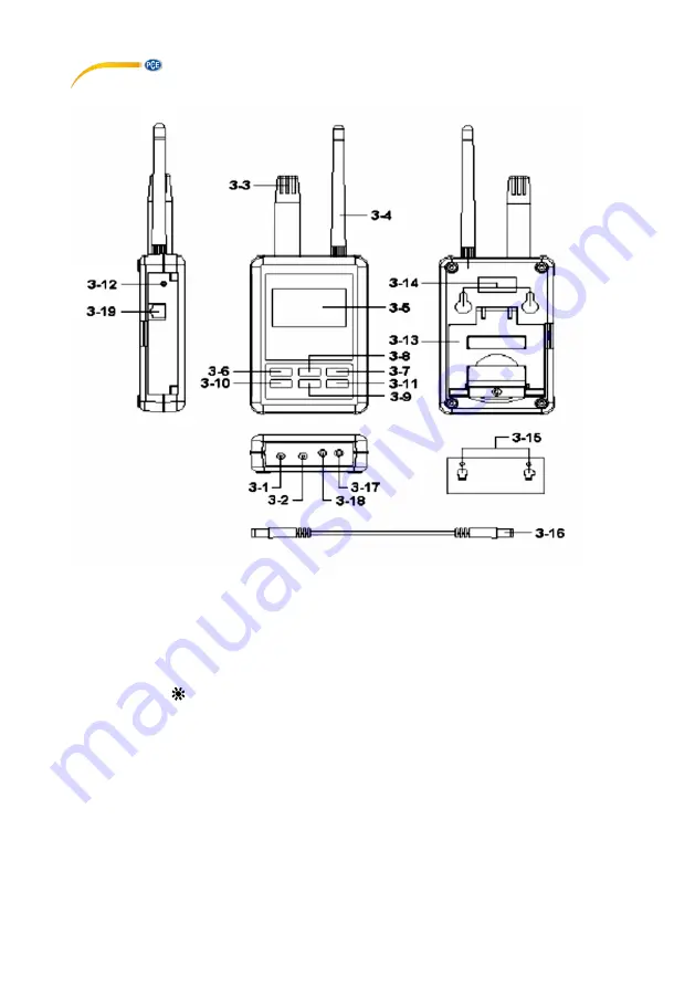
4 Device description
Fig.1
3.1 DC 9V power adapter input socket
3.11 ► button
3.2 DC 9V output socket
3.12 System reset button
3.3 Humidity/Temp. sensor
3.13 Stand
3.4 Antenna and antenna socket
3.14 Hanging holes
3.5 Display
3.15 Hanging unit (with sticker)
3.6 SETUP/ENTER BUTTON
3.16 Power interface cable/plugs
3.7 EXIT/SHIFT ( ) button
3.17 Isolate RS232 output socket
3.8 ▲ button
3.18 Pt1000 input socket
3.9 ▼ button
3.19 Network socket (RJ45)
3.10
◄
button


