background image

MANUAL: 55308 
REV:  A 
ECO:  49582 

13 

6.1.3  PCB CALIBRATION 

PROCEDURE 

Numerous precautions  are taken at PCB to insure 
accurate  and  repeatable  results.    This  section 
provides  a  brief  overview  of  the  primary  areas  of 
concern. 
 
Since the Back-to-Back Calibration technique relies 
on  each  sensor  experiencing  an  identical 
acceleration  level,  proper  mounting  of  the  test 
sensor  to  the  reference  standard  is  imperative.  
Sensors  with  mounting  holes  are  attached  directly 
to  the  reference  standard  with  a  stud  tightened  to 
the  recommended  mounting  torque.  A  shouldered 
mounting stud is typically used to prevent the stud 
from “bottoming out” in the hole.  
 
Both  mounting  surfaces  are  precision-machined 
and  lapped  to  provide  a  smooth,  flat  interface 
according  to  the  manufacturer’s  specification.    A 
thin layer of silicone grease is placed between the 
mating  surfaces  to  fill  any  imperfections  and 
increase  the  mounting  stiffness.    The  cables  are 
stress-relieved  by  first  routing  them  to  the  shaker 
head,  securing  them  with  tape  or  cable  ties,  then 
routing  them  to a  nearby  stationary  location.    This 
reduces cable motion, which is especially important 
when  testing  charge  output  sensors  and  helps  to 
prevent  extraneous  noise  or  stresses  from  being 
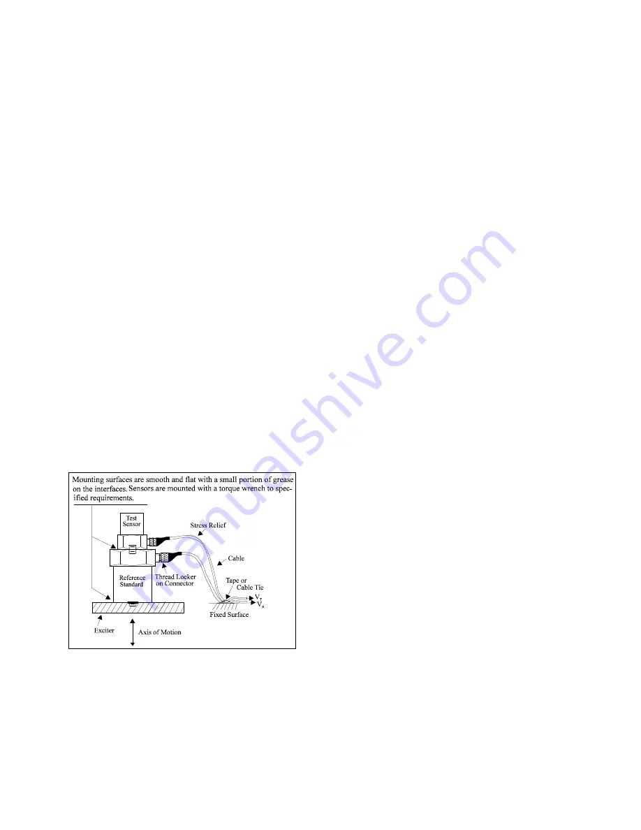
imparted into the system.  A typical set-up is shown 
in Figure 4.  


Figure 4.

 Typical Calibration Set-Up 

 
Adhesively mounted sensors use similar practices.  
However,  in  this  case,  a  small  portion  of  quick-
bonding  gel  or  similar  temporary  adhesive  is  used 
to  attach  the  test  sensor  to  a  reference  standard 
designed with a smooth, flat mounting surface. 

 
In addition to mounting, the selection of the proper 
equipment is critical.   Some of the more important 
considerations  include:  1)  the  reference  standard 
must be specified and previously calibrated over the 
frequency and/or amplitude range of interest; 2) the 
shaker  should  be  selected  to  provide  minimal 
transverse  (lateral)  motion  and  minimal  distortion; 
and  3)  the  quality  of  the  meters,  signal  generator, 
and  other  devices  should  be  selected  so  as  to 
operate within the limits of permissible error. 
 

7.4 COMMON MISTAKES 

Most  calibration  errors  are  caused  by  simply 
overlooking  some  of  the  fundamental  principals  of 
dynamics.  This section attempts to address some 
of the more common concerns. 
 
For  stud-mount  sensors,  always  mount  the 
accelerometer  directly  to  the  reference  standard.  
Ensure that the mounting surfaces are smooth, flat, 
and free of any burrs.  Always use a coupling fluid, 
such as silicone grease, in the mounting interface to 
maintain  a  high  mounting  stiffness.    Mount  the 
sensor 

according 

to 

the 

manufacturer’s 

recommended mounting torque.  DO NOT use any 
intermediate  mounting  adaptors,  as  the  mounted 
resonant  frequency  may  be  reduced  and  thereby 
compromise  the  high-frequency  performance.    If 
necessary, use adaptor studs. 


Содержание EX611A20

Страница 1: ...celerometer Installation and Operating Manual For assistance with the operation of this product contact PCB Piezotronics Inc Toll free 800 828 8840 24 hour SensorLine 716 684 0001 Fax 716 684 0987 E mail info pcb com Web www pcb com ...

Страница 2: ...ialized tests including sensitivity at elevated or cryogenic temperatures phase response extended high or low frequency response extended range leak testing hydrostatic pressure testing and others For more information contact your local PCB Piezotronics distributor sales representative or factory customer service representative Returning Equipment If factory repair is required our representatives ...

Страница 3: ...ation on particular operating steps The following symbols may be found on the equipment described in this manual This symbol on the unit indicates that high voltage may be present Use standard safety precautions to avoid personal contact with this voltage This symbol on the unit indicates that the user should refer to the operating instructions located in the manual This symbol indicates safety ea...

Страница 4: ...E 住房 O O O O O O PCB板 X O O O O O 电气连接器 O O O O O O 压电晶体 X O O O O O 环氧 O O O O O O 铁氟龙 O O O O O O 电子 O O O O O O 厚膜基板 O O X O O O 电线 O O O O O O 电缆 X O O O O O 塑料 O O O O O O 焊接 X O O O O O 铜合金 黄铜 X O O O O O 本表格依据 SJ T 11364 的规定编制 O 表示该有害物质在该部件所有均质材料中的含量均在 GB T 26572 规定的限量要求以下 X 表示该有害物质至少在该部件的某一均质材料中的含量超出 GB T 26572 规定的限量要求 铅是欧洲RoHS指令2011 65 EU附件三和附件四目前由于允许的豁免 CHINA RoHS COMPLIANCE ...

Страница 5: ... O Wires O O O O O O Cables X O O O O O Plastic O O O O O O Solder X O O O O O Copper Alloy Brass X O O O O O This table is prepared in accordance with the provisions of SJ T 11364 O Indicates that said hazardous substance contained in all of the homogeneous materials for this part is below the limit requirement of GB T 26572 X Indicates that said hazardous substance contained in at least one of t...

Страница 6: ...e with PIEZOELECTRIC CHARGE MODE ACCELEROMETERS SPECIFICATION SHEET INSTALLATION DRAWING AND CALIBRATION INFORMATION ENCLOSED PCB ASSUMES NO RESPONSIBILITY FOR DAMAGE CAUSED TO THIS PRODUCT AS A RESULT OF PROCEDURES THAT ARE INCONSISTENT WITH THIS OPERATING GUIDE ...

Страница 7: ...nnector 4 2 5 In Line Differential Charge Amplifier 4 3 INSTALLATION OVERVIEW 4 3 1 Equipment Inspection 4 3 2 Polarity Test 4 3 3 Sensor Location 4 3 4 Mounting Sensor 5 3 5 Route Mineral Insulated Hardline Cable 6 3 5 1 Care 6 3 5 2 Bend Radius 7 3 5 3 Clamp Cable 7 4 POWERING 8 4 1 Installation 8 4 2 Operation 8 5 HIGH TEMPERATURE OPERATION 8 5 1 Introduction 8 5 2 Reduced Resistance at Charge ...

Страница 8: ...ere high temperatures preclude the use of accelerometers with built in microelectronics Enclosed is a Specification Sheet which lists the complete performance characteristics of the particular accelerometer 2 CABLING 2 1 General Precautions and Considerations 2 1 1 Proper Cable Type and Care Ascertain that you have ordered the correct cable type Due to the high impedance nature of the output signa...

Страница 9: ...Charge Amplifier The differential charge amplifier is purchased separately A conventional method for conditioning the high impedance signal generated by a charge output sensor is to use a differential charge amplifiers operate from an ICP signal conditioner The unit employs a high gain amplifier to perform the impedance transformation The charge output of the transducers may be scaled in terms of ...

Страница 10: ...opriate charge amplifier specification sheet for information on low frequency characteristics Figure 1 Assorted Mounting Configurations and Their Effects on High Frequency 3 4 1 STUD MOUNT This mounting technique requires smooth flat contact surfaces for proper operation and is recommended for permanent and or secure installations Stud mounting is also recommended when testing at high frequencies ...

Страница 11: ...test object STEP 1 Prepare a smooth flat mounting surface A minimum surface finish of 63 in 0 00016 mm generally works best STEP 2 Stud mount the sensor to the appropriate adhesive mounting base according to the guidelines set forth in STEPS 2 and 3 of the Stud Mount Procedure STEP 3 Place a small portion of adhesive on the underside of the mounting base Firmly press down on the assembly to displa...

Страница 12: ...lamp Cable To minimize triboelectric motion induced noise from the cable interfering with the sensors high impedance charge output cable clamps must be used Clamp the cable as close to the transducer as possible and should be attached to the same surface that the head is mounted See Figure 3 taking care not to induce stress into the cable and possibly leading to intermittent or broken connections ...

Страница 13: ...ration Once each element is connected allow a few minutes for the system to thermally stabilize Place the switch on the charge amplifier in the OPERATE position and proceed with the measurement It is often convenient to normalize the accelerometer and charge amplifier system to a precise sensitivity such as 10 0 or 100 0 mV g for ease of data analysis This is accomplished with most PCB laboratory ...

Страница 14: ...evices As demonstrated in Equation 1 the steady state DC output voltage Eo is Equation 1 i f i o R R e E 1 This equation shows that if the input leakage resistance at the charge amplifier is extremely high approaching infinity the output DC voltage approaches ei usually a very tiny voltage However as Ri decreases the term i f R R 1 increases such that the output voltage can with large ratios of Rf...

Страница 15: ... mentioned and one comprised of series capacitor Cs and total equivalent shunt resistance Ri This new cutoff frequency is Equation 3 s i o C R 16 f To avoid compromise of the low frequency response established by the charge amplifier parameters and illustrated by Equation 2 the product of RiCs should be several orders of magnitude higher than RfCf The approximate final system discharge time consta...

Страница 16: ...ss checking against other equipment manufacturer recommendation and any risk associated with incorrect readings International standards such as ISO 10012 1 provide insight and suggested methods for determining recalibration intervals for most measuring equipment With the above information in mind and under normal circumstances PCB conservatively suggests a 12 to 24 month recalibration cycle for mo...

Страница 17: ...may be automated and vary depending on the type and number of accelerometers being calibrated Figure 2 Typical Back to Back Calibration System Because the acceleration is the same on both sensors the ratio of their outputs VT VR must also be the ratio of their sensitivities With the sensitivity of the reference standard SR known the exact sensitivity of the test sensor ST is easily calculated by u...

Страница 18: ...e 4 Typical Calibration Set Up Adhesively mounted sensors use similar practices However in this case a small portion of quick bonding gel or similar temporary adhesive is used to attach the test sensor to a reference standard designed with a smooth flat mounting surface In addition to mounting the selection of the proper equipment is critical Some of the more important considerations include 1 the...

Страница 19: ...ard Validate your calibration system with another accelerometer prior to each calibration session Check with the manufacturer for exact system specifications 7 5 CONCLUSIONS Without an adequate understanding of dynamics determining what when and how to test a sensor is a difficult task Therefore each user must weigh the cost time and risk associated with self calibration versus the services of an ...

Страница 20: ...ing Geometry Shear Shear Housing Material Inconel Inconel Sealing Hermetic Hermetic Size Height x Length x Width 787 in x 1 465 in x 1 456 in 20 mm x 37 mm x 37 mm Weight without cable 6 3 oz 180 gm 1 Electrical Connector LEMO PCA 0S 302 CLLC42 LEMO PCA 0S 302 CLLC42 Electrical Connection Position Side Side Cable Length 10 ft 3 m Cable Type MI Hardline Cable MI Hardline Cable Mounting Through Hole...

Страница 21: ...WING 49582 1 OF 1 1 5X MODEL EX611A20 DECIMALS XX 03 XXX 010 DECIMALS X 0 8 XX 0 25 BB 1 18 16 ECB 1 18 16 JJD 1 18 16 49582 PCB Piezotronics Inc claims proprietary rights in the information disclosed hereon Neither it nor any reproduction thereof will be disclosed to others without the written consent of PCB Piezotronics Inc REVISIONS REV DESCRIPTION DIN B UPDATED CABLE LENGTH 44951 98 25 0 1 46 ...

Страница 22: ...CRIPTION DIN NR RELEASED TO DRAFTING 45417 4 2 1 3 SCHEDULE DRAWING NO MODIFICATIONS PERMITTED WITHOUT REFERENCE TO THE NOTIFIED BODY CAUTION ELECTROSTATIC DISCHARGE SENSITIVE Ci AND Li BASED ON CABLE WITH 30 pF ft AND 33 μH ft WITH A MAXIMUM CABLE LENGTH OF 100ft Ci AND Li WILL BE DECREASED WITH SHORTER CABLE LENGTHS SHIELDS TO BE EARTHED AT BARRIER END THE INSTALLER SHALL INSURE THAT THE TRANSDU...

Страница 23: ...icator for Canada only Issued by Konstantin Rybalko Konstantin Rybalko PRODUCTS CLASS C225804 PROCESS CONTROL EQUIPMENT Intrinsically Safe Entity For Hazardous Locations CLASS C225884 PROCESS CONTROL EQUIPMENT Intrinsically Safe Entity For Hazardous Locations Certified to US Standards Class I Div 1 Group A B C D Class II Div 1 Group E F G Class III Div 1 Ex ia IIC T6 T710 Ga Class I Zone 0 AEx ia ...

Страница 24: ...6 of the NEC APPLICABLE REQUIREMENTS CSA C22 2 No 0 10 R2015 General requirements Canadian Electrical Code Part II C22 2 No 61010 1 12 Safety requirements for electrical equipment for measurement control and laboratory use Part 1 General requirements ANSI UL 61010 1 3rd Ed Electrical Equipment for Measurement Control and Laboratory Use Part 1 General Requirements C22 2 No 60079 0 2015 Explosive at...

Страница 25: ...1 103164_0_000 The products listed including the latest revision described below are eligible to be marked in accordance with the referenced Certificate Product Certification History Project Date Description 70089987 2016 08 09 Certification of EX611 Series High Temperature Vibration Sensor 65225 REV NR ECO 45417 ...

Страница 26: ...en installed per product documentation 2014 34 EU 2011 65 EU w 2015 863 EU ATEX Directive RoHS Directive Standards to which Conformity is Declared Harmonized Standards EN 60079 0 2012 A11 2013 EN 60079 11 2012 EN 63000 2018 General Explosive Atmosphere Intrinsic safe i Technical documentation for the assessment of electrical and electronic products with respect to the restriction of hazardous subs...

Страница 27: ... Protection Ex ia Marking Ex Ia IIC T6 T710t Ga lECEx LCIE 12 0002 X Approved for issue on behalf of the lECEx Julien GAUTHIER Certification Body Position Certification Officer Signature for printed version Date 2015 1109J 1 This certificate and schedule may only be reproduced in full 2 This certificate is not transferable and remains the property of the issuing body 3 The Status and authenticity ...

Страница 28: ...ranted subject to the conditions as set out in lECEx Scheme Rules lECEx 02 and Operational Documents as amended STANDARDS The electrical apparatus and any acceptable variations to it specified in the schedule of this certificate and the identified documents was found to comply with the following standards IEC 60079 0 2007 10 Explosive atmospheres Part 0 Equipment General requirements Edition 5 IEC...

Страница 29: ...output The vibration sensors provide a charge output when subjected to mechanical motion The sensors have stainless steel housings CONDITIONS OF CERTIFICATION YES as shown below The apparatus can be only connected to intrinsically safe certified equipment These combinations shall be compatible as regard intrinsic safety rules see drawing n52744 Ambient temperature of use 196C to 7009C Temperature ...

Страница 30: ...E 12 0002X Date of Issue 2015 11 09 Issue No I Page 4 of 4 DETAILS OF CERTIFICATE CHANGES for issues I and above Issue 01 Modification of QAR Addition of a manufacturing site Modification of the applicant name Annex lECEx LCIE 12 0002 X issue 01 Annex 01 pdf ...

Страница 31: ...Ga 2 lECEx LCIE 12 0002 X U 30V l lOOmA P 0 7W C 3300pF L1 30pH 1 completed by the model 2 temperature sensor and cable side Electrical parameters U1 30V l lOOmA P 0 7W C 3300pF L 30pH Page 1 of I This Annex is valid only in combination with certificate mentioned above and may only be reproduced in its entirety and without any change CERT ATEX FORM 14 Rev 00 ...

Страница 32: ...rking Ex ia llC T6 T710 C Ga Approved for issue on behalf of the lECEx Michel BRENON Certification Body Position Certification Officer Signature for printed version Date 1 This certificate and schedule may only be reproduced in full 2 This certificate is not transferable and remains the property of the issuing body 3 The Status and authenticity of this certificate may be verified by visiting the O...

Страница 33: ...ules lECEx 02 and Operational Documents as amended STANDARDS The electrical apparatus and any acceptable variations to it specified in the schedule of this certificate and the identified documents was found to comply with the following standards IEC 60079 0 2007 10 Explosive atmospheres Part 0 Equipment General requirements Edition 5 IEC 60079 11 2011 Explosive atmospheres Part 11 Equipment protec...

Страница 34: ...EX61 1XXXIXXXXX 1 Serial number Year of construction Ex ia IIC 16 T710 C Ga 2 lECEx LCIE 12 0002 X Ui 5 30V Ii 5 100mA P1 5 0 7W Ci 5 3300pF Li 5 30pH 1 completed by the model 2 temperature sensor and cable side Electrical parameters Ui 5 30V Ii 5 lOOmA Pi 5 0 7W Ci 5 3300pF Li 5 30pH CONDITIONS OF CERTIFICATION YES as shown below The apparatus can be only connected to intrinsically safe certified...

Страница 35: ...ective 2014 34 EU of the European Parliament and the Council of 26 February 2014 certifies that product has been found to comply with the Essential Health and Safety Requirements relating to the design and construction of products intended for use in potentially explosive atmospheres given in Annex II to the Directive Les résultats des vérifications et essais figurent dans le s rapport s confident...

Страница 36: ...rs de vibrations sont de type Vibration sensors types are as following EX611 Révision Revision une lettre one letter A Z M modèle spécial client customer special model Type de connecteur Connector type 00 mini mil 20 Lemo Longueur câble Cable length exemple example 020 20ft M020 20 m Type de connecteur spécial Specialty connector CARACTERISTIQUES RATINGS Paramètres électriques pour tous modèles av...

Страница 37: ...emperature greater than temperature classification mentioned according to operating temperature range 14 EXIGENCES ESSENTIELLES DE SANTE ET DE SECURITE ESSENTIAL HEALTH AND SAFETY REQUIREMENTS Couvertes par les normes listées au point 8 Covered by standards listed at 8 15 DOCUMENTS DESCRIPTIFS DESCRIPTIVE DOCUMENTS N Description Reference Rev Date Page s 1 Dossier technique ATEX Technical file ATE...

Страница 38: ...reproduced in its entirety and without any change It is issued in accordance with LCIE s ATEX Certification Rules CERT ATEX FORM 04 Rev 05 Page 4 4 1 Version 01 LCIE 12 ATEX 3053 X Issue 01 17 DETAILS DES MODIFICATIONS DE L ATTESTATION suite DETAILS OF CERTIFICATE CHANGES continued Version 01 Mise à jour normative selon la norme EN 60079 0 2012 A11 2013 Ajout d un modèle plus petit de base triangu...

Страница 39: ...spheres given in Annex II to the Directive The examination and test results are recorded in confidential report N01 13365 625323 9 Le respect des exigences essentielles de sécuritè et de 9 Compliance with the Essential Health and Safety sante est assure par la conformitè a Requirements has been assured by compliance with EN 60079 0 2009 EN 60079 11 2012 10 Le signe X lorsqu il est place a la suite...

Страница 40: ...ctive 94 9 CE 14 EC TYPE EXAMINATION CERTIFICATE LCIE 12 ATEX 3053 X 15 DESCRIPTION OF EQUIPMENT OR PROTECTIVE SYSTEM Vibration sensors Type EX611xxx xxxxx The apparatus is a vibration sensor series high temperature sensor with integral cable and connector output The vibration sensors provide a charge output when subjected to mechanical motion The sensors have stainless steel housings Specific par...

Отзывы: