MANUAL: 55308
REV: A
ECO: 49582
4
When using separate cables connect the cable to
the accelerometer. A small amount of thread-
locking compound placed on the connector prior to
attachment helps secure the cable during testing.
In harsh environments, the connection can be
sealed with silicone rubber, O-rings, and flexible
heat-shrink tubing.
2.3 Integral Hardline Cable
For extremely high temperature (>500°F) charge
mode applications use mineral insulated (MI)
hardline. Keep cable clean to maintain insulation
resistance and good low-frequency response
2.4 Hardline Connection Type
2.4.1 PCB / Lemo type connector
The Lemo connector is PCA.0S.302.CLAC42 that
is specially adapted for use with hardline cable.
The connector is a self-latching system that allows
the connector to be mated by simply pushing the
plug axially into the socket. When required the
connector is disengage by a single axial pull on the
outer release sleeve.
2.4.2 High Temperature 2
–pin 7/16-
27 UNS connector
This connector is a Model GP, 2 Pin Jack, 7/16-27
thread. The connector is welded to the hardline to
provide a high temperature, hermetic connection.
The GP connector uses a threaded connction to
mate with a GN or QY 2-Socket plug and torqued
to 5 ft*lbs +/- 1 ft*lb
2.5 Differential Charge Amplifier
The differential charge amplifier is purchased
separately
A conventional method for conditioning the high-
impedance signal generated by a charge output
sensor is to use a differential charge amplifiers
operate from an ICP ® signal conditioner. The unit
employs a high gain amplifier to perform the
impedance transformation. The charge output of
the transducers may be scaled in terms of
acceleration, pressure or force. The output is then
mV/g, mV/psi or mV/lb, respectively.
3
INSTALLATION
OVERVIEW
3.1 Equipment Inspection
Before installing the accelerometer, verify the
insulation resistance (I/R) of the sensor is per
specification. I/R can be out of specification due to
mishandling and/or damage.
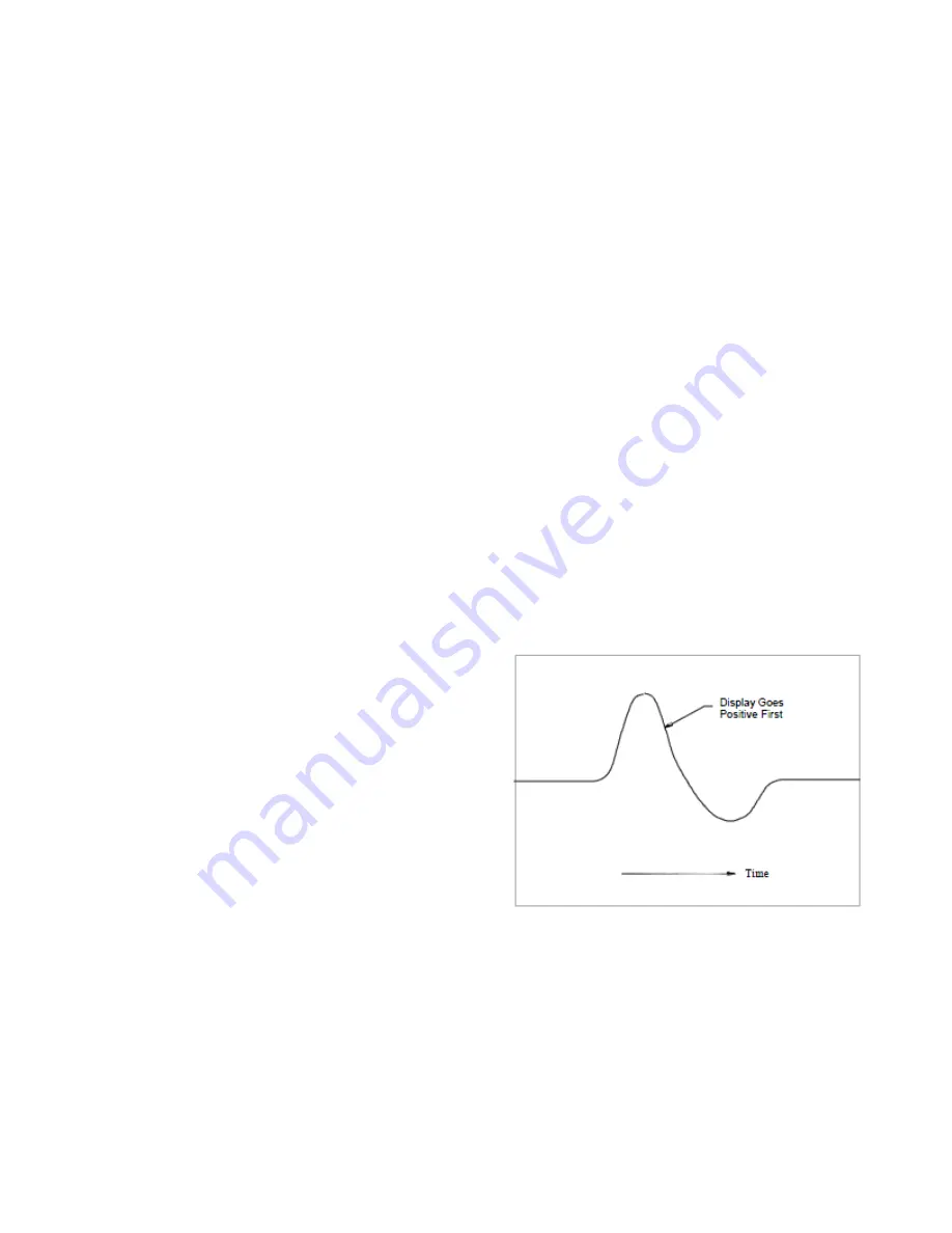
3.2 Polarity Test
Use this test to verify the proper polarity response.
Improper polarity will adversely affect the use of the
sensor for machinery diagnostics such as
balancing.
Step 1
– Connect the sensor to a charge amp and
any ICP ® signal conditioner. Using standard
cable, connect the powered sensor to an
oscilloscope.
Step 2
– Set the time scale to 20
milliseconds/division
Step 3
– Hold the transducer in hand and tap the
bottom. The wavefrom on the oscilloscope first
goes positive as shown in Figure 1. If the
waveform goes negative the wiring is reversed,
contact PCB for technical support.
FIGURE 1
3.3 Sensor Location
Characteristics like location, ruggedness,
amplitude range, accessibility, temperature, and
portability are extremely critical.


