


1. Collector Box Drain, Inducer Housing Drain, Relief Port, and Pressure Switch Tubes
These tubes should be factory attached to condensate trap and pressure switch ready for use in UPFLOW applications. These tubes can be
identified by their connection location and also by a color label on each tube. These tubes are identified as follows: collector box drain tube
(blue label), inducer housing drain tube (violet label or molded), relief port tube (green label), and pressure switch tube (pink label).
2. Condensate Trap Drain Tube
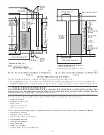
The condensate trap drain connection must be extended for field attachment by doing the following:
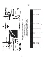
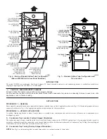
a. Determine location of field drain connection. (See Fig. 2 or 6.)
NOTE:
If internal filter is used, drain tube should be located to opposite side of casing from return duct attachment to assist in filter removal.
b. Remove and discard casing drain hole plug button from desired side.
c. Install drain tube coupling grommet (factory-supplied in loose parts bag) in selected casing hole.
d. Slide drain tube coupling (factory-supplied in loose parts bag) through grommet ensuring long end of coupling faces blower.
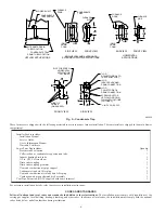
e. Cement 2 factory-supplied 1/2-in. street CPVC elbows to the rigid drain tube connection on the condensate trap. (See Fig. 6.) These
elbows must be cemented together and cemented to condensate trap drain connection.
NOTE:
Failure to use CPVC elbows may allow drain to kink and prevent draining.
f. Connect larger diameter drain tube and clamp (factory-supplied in loose parts bag) to condensate trap and clamp securely.
g. Route tube to coupling and cut to appropriate length.
h. Attach tube to coupling and clamp securely.
C.
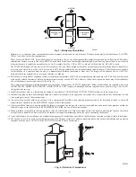
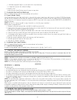
Condensate Trap Location (Alternate Upflow Orientation)
An alternate location for the condensate trap is the left-hand side of casing. (See Fig. 2 and 7.)
NOTE:
If the alternate left-hand side of casing location is used, the factory-connected drain and relief port tubes must be disconnected and
modified for attachment. See Condensate Trap Tubing (Alternate Upflow Orientation) section for tubing attachment.
To relocate condensate trap to the left-hand side, perform the following:
1. Remove 3 tubes connected to condensate trap.
2. Remove trap from blower shelf by gently pushing tabs inward and rotating trap.
3. Install casing hole filler cap (factory-supplied in loose parts bag) into blower shelf hole where trap was removed.
WARNING: CARBON MONOXIDE POISONING HAZARD
Failure to follow this warning could result in personal injury or death.
Casing hole filler cap must be installed in blower shelf hole when condensate trap is relocated to prevent combustion products being
drawn in from appliances in the equipment room.
4. Install condensate trap into left-hand side casing hole by inserting tube connection stubs through casing hole and rotating until tabs snap
into locking position.
5. Fill unused condensate trap casing holes with plastic filler caps (factory-supplied in loose parts bag).
D.
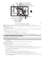
Condensate Trap Tubing (Alternate Upflow Orientation)
NOTE:
See Fig. 7 or tube routing label on main furnace door to confirm location of these tubes.
1. Collector Box Drain Tube
Connect collector box drain tube (blue label) to condensate trap.
NOTE:
On 17-1/2-in. wide furnaces ONLY, cut tube between corrugated sections to prevent kinks from occurring.
2. Inducer Housing Drain Tube
a. Remove and discard LOWER (molded) inducer housing drain tube which was previously connected to condensate trap.
b. Use inducer housing drain extension tube (violet label and factory-supplied in loose parts bag) to connect LOWER inducer housing drain
connection to the condensate trap.
c. Determine appropriate length, cut, and connect tube.
d. Clamp tube to prevent any condensate leakage.
3. Relief Port Tube
a. Connect relief port tube (green label) to condensate trap.
b. Extend this tube (if required) by splicing to small diameter tube (factory-supplied in loose parts bag).
c. Determine appropriate length, cut, and connect tube.
E.
Condensate Trap Field Drain Attachment
Refer to Condensate Drain section for recommendations and procedures.
F.
Pressure Switch Tubing
The LOWER collector box pressure tube (pink label) is factory connected to the pressure switch and should not require any modification.
NOTE:
See Fig. 6 or 7 or tube routing label on main furnace door to check for proper connections.
—9—
→
Содержание PG9MAA
Страница 70: ... 70 ...
Страница 71: ... 71 ...
Страница 72: ... 2005 Payne Heating Cooling 7310 W Morris St Indianapolis IN 46231 72 impg9m10 Catalog No 53PG 9M29 ...


