


NOTE:
Proper polarity must be maintained for 115-v wiring. If polarity is incorrect, control center LED status indicator light will flash rapidly
and furnace will NOT operate.
WARNING: ELECTRICAL SHOCK AND FIRE HAZARD
Failure to follow this warning could result in serious injury, death, or property damage.
The cabinet MUST have an uninterrupted or unbroken ground according to NEC ANSI/NFPA 70-2002 and Canadian Electrical Code
CSA C22.1 or local codes to minimize personal injury if an electrical fault should occur. This may consist of electrical wire or conduit
approved for electrical ground when installed in accordance with existing electrical codes. Do not use gas piping as an electrical
ground.
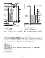
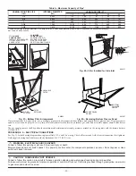
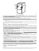
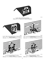
J-BOX RELOCATION
1. Remove 2 screws holding auxiliary J-box. (See Fig. 33.)
2. Rotate J-box 180° and attach box to right side, using holes provided.
WARNING: ELECTRICAL SHOCK AND FIRE HAZARD
Failure to follow this warning could result in serious injury, death, or property damage.
If manual disconnect switch is to be mounted on furnace, select a location where a drill or fastener will not contact electrical or gas
components.
B.
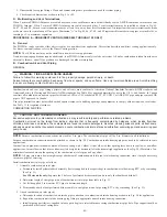
24-v Wiring
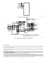
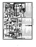
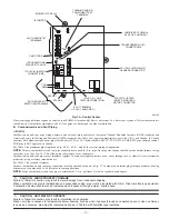
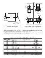
Make field 24-v thermostat connections at 24-v terminal block on furnace control center. For proper cooling operation, Y wire from thermostat
MUST be connected to Y terminal on control center, as shown in Fig. 31. The 24-v terminal block is marked for easy connection of field wiring.
(See Fig. 34.) The 24-v circuit contains a 3-amp, automotive-type fuse located on furnace control center. (See Fig. 35.) Any electrical shorts of
24-v wiring during installation, service, or maintenance may cause fuse to blow. If fuse replacement is required, use only a fuse of identical size
(3 amp) and type. The control will flash code 24 when fuse needs replacement.
NOTE:
Use AWG No. 18 color-coded copper thermostat wire for lengths up to 100 ft. For wire lengths over 100 ft, use AWG No. 16 wire.
C.
Accessories
1. Electronic Air Cleaner (EAC)
Two quick-connect terminals marked EAC-1 and EAC-2 are provided for EAC connection. (See Fig. 35.) These terminals are energized
with 115v (1.0-amp maximum) during blower motor operation.
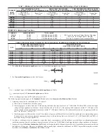
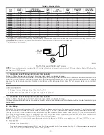
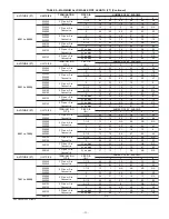
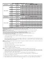
Table 6—Electrical Data
UNIT
SIZE
VOLTS—
HERTZ—
PHASE
OPERATING
VOLTAGE RANGE
MAX
UNIT
AMPS
UNIT
AMPACITY†
MIN
WIRE
GAUGE
MAX WIRE
LENGTH
(FT)‡
MAX FUSE
OR CKT BKR
AMPS**
Max*
Min*
024040
115—60—1
127
104
6.1
8.4
14
44
15
036040
115—60—1
127
104
7.3
10.0
14
37
15
024060
115—60—1
127
104
6.1
8.4
14
44
15
036060
115—60—1
127
104
7.1
9.8
14
38
15
048060
115—60—1
127
104
9.5
12.8
14
29
15
036080
115—60—1
127
104
7.6
10.4
14
36
15
048080
115—60—1
127
104
10.0
13.4
14
28
15
060080
115—60—1
127
104
14.1
18.4
12
31
20
048100
115—60—1
127
104
10.2
13.5
14
27
15
060100
115—60—1
127
104
14.8
19.3
12
30
20
060120
115—60—1
127
104
14.6
19.1
12
30
20
060140
115—60—1
127
104
14.3
18.8
12
30
20
* Permissible limits of voltage range at which unit will operate satisfactorily.
† Unit ampacity = 125 percent of full load amps of largest operating component plus 100 percent of full load amps of all other potential operating components (EAC,
humidifier, etc.).
‡ Length shown is as measured 1 way along wire path between unit and service panel for maximum 2 percent voltage drop.
** Time-delay type is recommended.
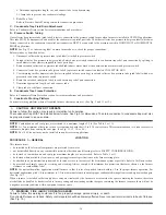
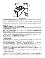
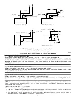
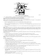
Fig. 32—Disconnect Switch and Furnace
A93033
COPPER
WIRE ONLY
ELECTRIC
DISCONNECT
SWITCH
ALUMINUM
WIRE
—30—
→
Содержание PG9MAA
Страница 70: ... 70 ...
Страница 71: ... 71 ...
Страница 72: ... 2005 Payne Heating Cooling 7310 W Morris St Indianapolis IN 46231 72 impg9m10 Catalog No 53PG 9M29 ...


