background image

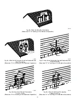
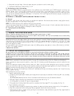
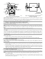
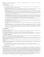
An abandoned masonry chimney may be used as a raceway for a properly insulated and supported vent pipe. Each furnace must have its own vent
pipe and be terminated individually.
Other gas appliances with their own venting system may also use the abandoned chimney as a raceway providing it is permitted by local code,
the current edition of the NFGC or NSCNGPIC, and the vent or liner manufacturer’s Installation Instructions. Care must be taken to prevent the
exhaust gases from one appliance from contaminating the combustion air of other gas appliances.

WARNING: CARBON MONOXIDE AND PROPERTY DAMAGE HAZARD

Failure to follow this warning could result in property damage, personal injury, or death.
Vent pipes must be airtight and watertight.

NOTE:

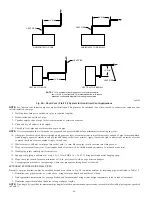
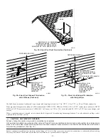
The minimum vent pipe length for these furnaces is 5 ft. Short pipe lengths (5-8 ft) may discharge water droplets. These droplets may

be undesirable; therefore, a 12-in. minimum offset pipe section is recommended to reduce excessive droplets from exiting vent pipe outlet. (See
Fig. 54.)

NOTE:

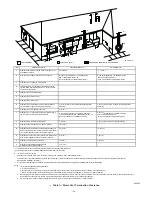
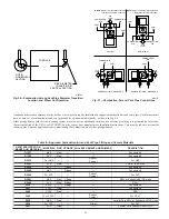
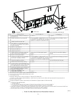
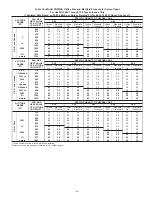
Do not count elbows or pipe sections in terminations or within furnace. See shaded areas in Fig. 56.

EXAMPLE:
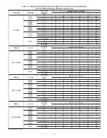
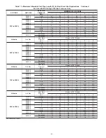
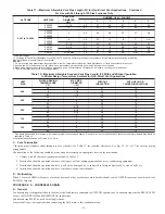
An 036080 size furnace located in Indianapolis, elevation 650 ft above sea level, could be installed in an application requiring 3 elbows
and 32 ft of vent pipe. Table 11 indicates this application would allow a 2-in. diameter vent pipe. At 0-2000 ft elevation, 2-in. pipe is good
for up to 35 ft with 3 elbows. If same installation were in Albuquerque, elevation 5250 ft above sea level, installation would require 2-1/2
in. vent pipe. At 5001- to 6000-ft elevation, 2-in. pipe is allowed for up to 23 ft with 3 elbows, but 2-1/2 in. pipe can be used for up to
70 ft with 3 elbows.

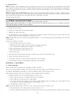
Install vent pipe as follows:

1. Determine location of vent pipe connection to inducer housing as shown in Fig. 50 for application.

2. Reposition neoprene inducer housing outlet cap and clamp to appropriate unused inducer housing connection. Tighten clamp.

CAUTION: UNIT DAMAGE HAZARD

Failure to follow this caution could result in unit component damage.
Inducer housing outlet cap must be installed and fully seated against inducer housing. Clamp must be tightened to prevent any
condensate leakage.

3. Install pipe support (factory-supplied in loose parts bag) into selected furnace casing vent pipe hole. Pipe support should be positioned at

bottom of casing hole.

4. Be certain that mating surfaces of inducer housing connection, elastomeric coupling, and 2-in. diameter vent pipe are clean and dry.

Assemble the elastomeric (rubber) vent coupling (with 2 loose clamps) onto inducer housing connection. Insert the 2-in. diameter vent pipe
through the elastomeric (rubber) coupling and fully into inducer housing connection until it bottoms on the internal stop. Tighten both
clamps to secure the pipe to inducer housing. Tighten the clamp screws to 15 in.-lb. of torque.

CAUTION: UNIT DAMAGE HAZARD

Failure to follow this caution may result in unit component damage.
Vent pipe must be installed and fully seated against inducer housing. Clamp must be tightened to prevent any condensate leakage.

NOTE:

A 2-in. diameter pipe must be used within the furnace casing. Make all pipe diameter transitions outside furnace casing.

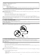
VENT EXTENSION PIPE

Some furnaces are supplied with a PVC vent extension pipe (2-in. diameter by 12-in. long). This pipe has a built-in channel to assist vent
condensate disposal. When this vent extension pipe is supplied, it must be used to connect the field vent pipe to furnace inducer housing
on ALL upflow and downflow applications.

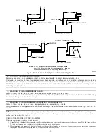
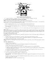
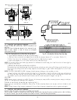
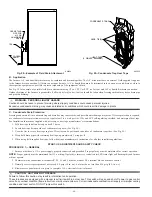
Fig. 52—Intake Housing Plug Fitting Drain

A96190

COMBUSTION–
AIR PIPE

BURNER
BOX

COMBUSTION–AIR
INTAKE HOUSING

3/8

 ID TUBE

TRAP

TO OPEN

DRAIN

3/16

DRILL

HOUSING

PLUG

4

MIN

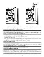
Fig. 53—Vent Pipe Diameter Transition Location

and Elbow Configuration

A93034

FURNACE

PIPE DIAMETER

TRANSITION IN

VERTICAL SECTION

NOT IN
HORIZONTAL
SECTION

—47—

Содержание PG9MAA

Страница 1: ...e to Cooling Equipment 17 Location with Respect to Combustion and Circulating Air Requirements 18 Hazardous Locations 18 AIR FOR COMBUSTION AND VENTILATION 19 INSTALLATION 22 Leveling Legs If Desired 22 Installation In Upflow or Downflow Applications 22 Installation In Horizontal Applications 24 Air Ducts 24 General 24 Ductwork Acoustical Treatment 24 Supply Air Connections 25 As an ENERGY STAR Pa...

Страница 2: ...e excessive servicing or cause premature component failure Application of this furnace should be indoors with special attention given to vent sizing and material gas input rate air temperature rise unit leveling and unit sizing WARNING FIRE EXPLOSION ELECTRICAL SHOCK AND CARBON MONOXIDE POISONING HAZARD Failure to follow this warning could result in electrical shock fire personal injury or death I...

Страница 3: ...earance to combustibles 0 0 po Dégagement d évent avec combustibles Dégagement avant minimum de 610mm 24 po pour l entretien Pour les fournaises de 140 taille 1 po 25mm dégagement des matériaux combustibles est requis au arriere This furnace is approved for UPFLOW DOWNFLOW and HORIZONTAL installations Cette fournaise est approuvée pour l installation HORIZONTALE et la circulation d air VERS LE HAU...

Страница 4: ...on of 1 side and the bottom or the bottom only will ensure adequate return air openings for airflow requirements above 1800 CFM at 0 5 W C ESP 17 5 16 24 1 2 27 9 16 TYP 27 5 8 29 11 16 TYP 30 13 16 32 5 8 TYP 33 1 4 TYP CONDENSATE DRAIN TRAP LOCATION ALTERNATE UPFLOW 7 8 IN DIA ACCESSORY POWER ENTRY 7 8 IN DIA POWER CONN CONDENSATE DRAIN TRAP LOCATION DOWNFLOW HORIZONTAL LEFT 26 15 16 24 1 2 22 5...

Страница 5: ... required when used in DOWNFLOW HORIZONTAL RIGHT or HORIZONTAL LEFT supply air discharge direction applications as shown in Fig 3 See details in Applications section Install this furnace only in a location and position as specified in LOCATION and INSTALLATION sections of these instructions Combustion products must be discharged outdoors Connect this furnace to an approved vent system only as spec...

Страница 6: ...es and standards in addition to these instructions The installation must comply with regulations of the serving gas supplier local building heating plumbing and other codes In absence of local codes the installation must comply with the national codes listed below and all authorities having jurisdiction Fig 5 Condensate Trap A93026 1 2 OD INDUCER HOUSING DRAIN CONNECTION 1 4 OD COLLECTOR BOX TO TR...

Страница 7: ...ches 915 mm 3 When lever handle type manual equipment shutoff valves are used they shall be T handle valves 4 The use of copper tubing for gas piping is NOT approved by the state of Massachusetts PROCEDURE 7 ELECTRICAL CONNECTIONS US National Electrical Code NEC ANSI NFPA 70 2002 CANADA Canadian Electrical Code CSA C22 1 ELECTROSTATIC DISCHARGE ESD PRECAUTIONS CAUTION UNIT DAMAGE HAZARD Failure to...

Страница 8: ...nnected for UPFLOW applications A factory supplied tube is used to extend the condensate trap drain connection to the desired furnace side for field drain attachment See Condensate Trap Tubing Factory Shipped Orientation section for drain tube extension details See Fig 5 B Condensate Trap Tubing Factory Shipped Orientation NOTE See Fig 6 or tube routing label on main furnace door to confirm locati...

Страница 9: ... relocate condensate trap to the left hand side perform the following 1 Remove 3 tubes connected to condensate trap 2 Remove trap from blower shelf by gently pushing tabs inward and rotating trap 3 Install casing hole filler cap factory supplied in loose parts bag into blower shelf hole where trap was removed WARNING CARBON MONOXIDE POISONING HAZARD Failure to follow this warning could result in p...

Страница 10: ...on perform the following 1 Remove 3 tubes connected to condensate trap 2 Remove trap from blower shelf by gently pushing tabs inward and rotating trap 3 Install casing hole filler cap factory supplied in loose parts bag into blower shelf hole where trap was removed WARNING CARBON MONOXIDE POISONING HAZARD Failure to follow this warning could result in personal injury or death Casing hole filler ca...

Страница 11: ...nnect inducer housing drain connection to condensate trap Condensate Trap Located on Left Side of Casing 1 Determine appropriate length and cut 2 Connect tube to condensate trap 3 Clamp tube to prevent any condensate leakage Condensate Trap Located on Right Side of Casing 1 Route inducer housing drain tube violet label directly from inducer housing to condensate trap as shown in Fig 9 2 Determine ...

Страница 12: ...se parts bag B Condensate Trap Tubing NOTE See Fig 10 or tube routing label on main furnace door to check for proper connections 1 Collector Box Drain Tube a Install drain tube coupling factory supplied in loose parts bag into collector box drain tube blue label which was previously connected to condensate trap b Connect large diameter drain tube and clamp factory supplied in loose parts bag to dr...

Страница 13: ...nimum length of 5 ft See Table 9 or 11 NOTE A 12 in minimum offset pipe section is recommended with short 5 to 8 ft vent systems This recommendation is to reduce excessive condensate droplets from exiting the vent pipe See Fig 11 12 38 or 54 NOTE The 140 Size unit may not be installed in non direct vent applications PROCEDURE 5 HORIZONTAL RIGHT SUPPLY AIR DISCHARGE APPLICATIONS A horizontal right ...

Страница 14: ...REQUIRE A DRAIN PAN UNDER THE FURNACE AND CONDENSATE TRAP WHEN A CONDENSING FURNACE IS INSTALLED ABOVE FINISHED CEILINGS COMBUSTION AIR INTAKE Fig 11 Attic Location and Working Platform for Direct Vent Applications All Sizes A93031 COMBUSTION AIR INTAKE VENT MANUAL SHUTOFF GAS VALVE SEDIMENT TRAP CONDENSATE TRAP DRAIN ACCESS OPENING FOR TRAP 30 MIN WORK AREA A 12 IN MIN HORIZONTAL PIPE SECTION IS ...

Страница 15: ...unused condensate trap casing holes with plastic filler caps factory supplied in loose parts bag B Condensate Trap Tubing NOTE See Fig 13 or tube routing label on main furnace door to check for proper connections 1 Collector Box Drain Tube a Remove factory installed plug from LOWER collector box drain tube blue and white striped label b Install removed clamp and plug into UPPER collector box drain...

Страница 16: ...may result in intermittent unit operation The condensate trap MUST be installed below furnace See Fig 5 for dimensions The drain connection to condensate trap must also be properly sloped to an open drain NOTE Combustion air and vent pipes are restricted to a minimum length of 5 ft See Table 9 or 11 NOTE A 12 in minimum offset pipe section is recommended with short 5 to 8 ft vent systems This reco...

Страница 17: ...te and the firing rate has been set to the nameplate value The filters used to clean the circulating air during the construction process must be either changed ot thoroughly cleaned prior to occupancy The furnace ductwork and filters are cleaned as necessary to remove drywall dust and construction debris from all HVAC system components after construction is completed After construction is complete...

Страница 18: ... atmosphere unit must be installed in accordance with NFGC or NSCNGPIC See Fig 17 PROCEDURE 4 HAZARDOUS LOCATIONS A Direct Vent Applications Furnace may be located in a confined space without special provisions for dilution or ventilation air B Non Direct Vent Applications CAUTION UNIT DAMAGE HAZARD Failure to follow this caution may result in intermittent unit operation Do not install furnace in ...

Страница 19: ...ir may be required for combustion Permanent wave solutions Chlorinated waxes and cleaners Chlorine based swimming pool chemicals Water softening chemicals De icing salts or chemicals Carbon tetrachloride Halogen type refrigerants Cleaning solvents such as perchloroethylene Fig 18 Air for Combustion Ventilation and Dilution for Outdoors A03174 1 SQ IN PER 4000 BTUH DUCTS TO OUTDOORS 1 SQ IN PER 400...

Страница 20: ...ned input for all gas appliances in the space per Fig 18 and Table 1 d TWO OPENINGS OR VERTICAL DUCTS require 1 square inch of free area per 4 000 Btuh 550 mm2 kW for combined input of all gas appliances in the space per Fig 18 and Table 1 3 ONE OUTDOOR OPENING requires a 1 square inch of free area per 3 000 Btuh 734 mm2 kW for combined input of all gas appliances in the space per Table 1 and b No...

Страница 21: ...ent ventilation and dilution of flue gases However in buildings with unusually tight construction additional air MUST be provided using the methods described in the Outdoor Combustion Air Method section Table 1 Minimum Free Area Required for Each Combustion Air Opening or Duct to Outdoors FURNACE INPUT BTUH TWO HORIZONTAL DUCTS 1 SQ IN 2 000 BTUH 1 100 SQ MM KW SINGLE DUCT OR OPENING 1 SQ IN 3 000...

Страница 22: ...nd drill a 5 16 in diameter hole in each bottom corner of furnace See Fig 20 Holes in bottom closure panel may be used as guide locations 2 For each hole install nut on bolt and then install bolt and nut in hole Install flat washer if desired 3 Install another nut on other side of furnace base Install flat washer if desired 4 Adjust outside nut to provide desired height and tighten inside nut to s...

Страница 23: ...plications on Combustible Flooring NOT Using KGASB Subbase Furnace with CD5 CK5 Coil Assembly or KCAKC Coil Box 19 19 20 20 24 1 2 Upflow Applications 23 24 1 8 23 5 8 24 3 4 Downflow Applications on Non Combustible Flooring 22 7 8 19 23 1 2 19 5 8 Downflow Applications on Combustible Flooring Using KGASB Subbase Furnace with or without CD5 CK5 Coil Assembly or KCAKC Coil Box 22 1 8 19 23 3 4 20 3...

Страница 24: ...tors National Association SMACNA or American Society of Heating Refrigerating and Air Conditioning Engineers ASHRAE or consult The Air Systems Design Guidelines reference tables available from your local distributor The duct system should be sized to handle the required system design CFM at the design static pressure When a furnace is installed so that the supply ducts carry air circulated by the ...

Страница 25: ...upply air opening on furnace The supply air duct attachment must ONLY be connected to furnace supply outlet or air conditioning coil casing when used DO NOT cut main furnace casing to attach supply side air duct humidifier or other accessories All accessories MUST be connected external to furnace main casing D Return Air Connections The furnace and its return air system shall be designed and insta...

Страница 26: ... operate a unit without a filter or with filter access door removed Factory supplied washable framed filters are shipped in blower compartment Determine location for filter and relocate filter retaining wire if necessary See Table 4 to determine correct filter size for desired filter location Table 4 indicates filter size location and quantity shipped with furnace See Fig 2 for location and size o...

Страница 27: ...ifically for the detection of leaks to check all connections Use proper length of pipe to avoid stress on gas control manifold If a flexible connector is required or allowed by authority having jurisdiction black iron pipe shall be installed at furnace gas valve and extend a minimum of 2 in outside furnace casing Install a sediment trap in riser leading to furnace Trap can be installed by connecti...

Страница 28: ...ON FURNACE MAY NOT OPERATE Failure to follow this caution may result in furnace operation stopping and water pipes freezing during cold weather Furnace control must be grounded for proper operation or control will lock out Control is grounded through green yellow wire routed to gas valve and burner box screw Table 5 Maximum Capacity of Pipe NOMINAL IRON PIPE SIZE IN INTERNAL DIAMETER IN LENGTH OF ...

Страница 29: ...arate fused branch electrical circuit containing a properly sized fuse or circuit breaker for this furnace See Table 6 for wire size and fuse specifications A disconnecting means must be located within sight from and readily accessible to furnace Fig 30 Typical Gas Pipe Arrangement A93324 UNION SEDIMENT TRAP MANUAL SHUTOFF VALVE REQUIRED GAS SUPPLY Fig 31 Heating and Cooling Application Wiring Dia...

Страница 30: ...wiring during installation service or maintenance may cause fuse to blow If fuse replacement is required use only a fuse of identical size 3 amp and type The control will flash code 24 when fuse needs replacement NOTE Use AWG No 18 color coded copper thermostat wire for lengths up to 100 ft For wire lengths over 100 ft use AWG No 16 wire C Accessories 1 Electronic Air Cleaner EAC Two quick connect...

Страница 31: ...ere is no blockage or restriction leakage corrosion and other deficiencies which could cause an unsafe condition 3 As far as practical close all building doors and windows and all doors between the space in which the appliance s connected to the venting system are located and other spaces of the building 4 Close fireplace dampers 5 Turn on clothes dryers and any appliance not connected to the vent...

Страница 32: ...RAFT MOTOR PSC IDR INDUCED DRAFT MOTOR RELAY SPST N O ILK BLOWER ACCESS PANEL INTERLOCK SWITCH SPST N O J1 BLOWER OFF DELAY JUMPER SELECTOR J2 COOLING OFF DELAY JUMPER JB JUNCTION BOX LED LIGHT EMITTING DIODE FOR STATUS CODES RED LGPS LOW GAS PRESSURE SWITCH SPST N O LS LIMIT SWITCH AUTO RESET SPST N C OL AUTO RESET INTERNAL MOTOR OVERLOAD TEMPERATURE SWITCH N C PCB PRINTED CIRCUIT BOARD CONTROL P...

Страница 33: ... plug fitting and inducer housing alternate vent cap may need to be relocated in some applications NOTE Slope combustion air and vent pipes a minimum of 1 4 in per linear ft with no sags between hangers CAUTION MINOR PROPERTY DAMAGE Failure to follow this caution may result in water damage from condensate dripping When combustion air pipe is installed above a suspended ceiling pipe must be insulat...

Страница 34: ...terline extended above or below vent terminal of the furnace to a dryer or water heater vent or other appliance s direct vent intake or exhaust 12 30 cm 12 30 cm O Clearance from a plumbing vent stack 3 91 cm 3 91 cm 1 In accordance with the current CSA B149 1 Natural Gas and Propane Installation Code 2 In accordance with the current ANSI Z223 1 NFPA 54 National Fuel Gas Code 18 46 cm above roof s...

Страница 35: ...ION AIR AIR FLOW VENT VENT VENT AIR FLOW AIR FLOW AIR FLOW UPFLOW DOWNFLOW HORIZONTAL LEFT DISCHARGE HORIZONTAL RIGHT DISCHARGE Select 1 vent pipe connection and 1 combustion air pipe connection COMBUSTION AIR COMBUSTION AIR COMBUSTION AIR COMBUSTION AIR VENT VENT VENT NOTE Select 1 vent pipe connection and 1 combustion air pipe connection NOTE Table 8 Approved Combustion Air and Vent Pipe Fitting...

Страница 36: ...d 44 NOTE The minimum combustion air and vent pipe length each for these furnaces is 5 ft Short pipe lengths 5 8 ft may discharge water droplets These droplets may be undesirable therefore a 12 in minimum offset pipe section is recommended to reduce excessive droplets from exiting vent pipe outlet See Fig 38 COMBUSTION AIR AND VENT PIPE DIAMETER Determine combustion air and vent pipe diameter 1 Us...

Страница 37: ... air intake housing since it may be necessary to remove pipe for service of igniter or flame sensor COMBUSTION AIR INTAKE HOUSING PLUG FITTING The combustion air intake plug fitting must be installed in unused combustion air intake housing This fitting must be attached by using RTV sealant or by drilling a 1 8 in hole in fitting using hole in intake housing as a guide Install a field supplied No 6...

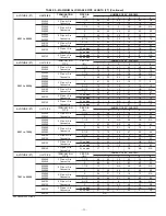
Страница 38: ...70 70 70 70 2 Pipe or 2 in Concentric 1 1 2 17 12 7 NA NA NA 024060 036060 048060 2 70 67 66 61 61 61 036080 048080 060080 2 Pipe or 2 in Concentric 2 49 44 30 25 25 15 2 1 2 70 70 70 70 70 70 048100 060100 2 Pipe or 3 in Concentric 2 1 2 35 26 16 16 6 NA 3 70 70 70 70 66 61 060120 2 Pipe or 3 in Concentric 3 14 9 NA NA NA NA 3 no disk 70 70 63 56 50 43 4 no disk 70 70 70 70 70 70 060140 2 Pipe or...

Страница 39: ...ipe or 3 in Concentric 3 no disk 42 35 29 22 15 9 4 no disk 70 70 70 70 70 70 060140 2 Pipe or 3 in Concentric 3 no disk 12 8 NA NA NA NA 4 no disk 42 37 32 27 22 17 ALTITUDE FT UNIT SIZE TERMINATION TYPE PIPE DIA IN NUMBER OF 90 ELBOWS 1 2 3 4 5 6 6001 to 7000 024040 036040 2 Pipe or 2 in Concentric 1 1 2 53 48 43 38 37 32 2 70 70 68 67 66 64 024060 036060 048060 2 Pipe or 2 in Concentric 1 1 2 1...

Страница 40: ...E TERMINATION TYPE PIPE DIA IN NUMBER OF 90 ELBOWS 1 2 3 4 5 6 8001 to 9000 024040 036040 2 Pipe or 2 in Concentric 1 1 2 46 41 36 31 29 24 2 62 60 58 56 55 53 024060 036060 048060 2 Pipe or 2 in Concentric 1 1 2 11 6 NA NA NA NA 2 49 44 42 37 35 34 036080 048080 060080 2 Pipe or 2 in Concentric 2 33 28 17 12 10 NA 2 1 2 62 60 58 56 55 53 048100 060100 2 Pipe or 3 in Concentric 2 1 2 23 15 7 5 NA ...

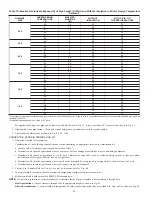
Страница 41: ...ombustion air and vent pipe diameters as stated above using total pipe length and number of elbows 2 Using winter design temperature used in load calculations find appropriate temperature for your application and furnace model 3 Determine required insulation thickness for exposed pipe lengths NOTE Pipe length ft specified for maximum pipe lengths located in unconditioned spaces cannot exceed total...

Страница 42: ...centric vent air termination components together using instructions in kit 4 Slide assembled kit with rain shield REMOVED through hole NOTE Do not allow insulation or other materials to accumulate inside of pipe assembly when installing it through hole Roof terminations Locate assembly through roof to appropriate height as shown in Fig 41 Sidewall terminations Locate assembly through sidewall with...

Страница 43: ...COMBUSTION AIR COUPLING ROOF VENT BRACKET VERTICAL SEPARATION BETWEEN COMBUSTION AIR AND VENT 8 3 4 FOR 3 KIT 6 3 4 FOR 2 KIT MAINTAIN 12 IN MINIMUM CLEARANCE ABOVE HIGHEST ANTICIPATED SNOW LEVEL MAXIMUM OF 24 IN ABOVE ROOF Fig 44 Direct Vent Sidewall Termination of Less than 12 in A87226 MAINTAIN 12 IN CLEARANCE ABOVE HIGHEST ANTICIPATED SNOW LEVEL OR GRADE WHICHEVER IS GREATER 90 VENT 12 IN SEPA...

Страница 44: ...aration A93056 COMBUSTION AIR VENT VENT A Fig 45 Direct Vent Rooftop Termination Dimension A is Touching or 2 In Maximum Separation A96128 A Fig 49 Direct Vent Sidewall Termination of More Than 12 In Dimension A is Touching or 2 In Maximum Separation A96130 COMBUSTION AIR COMBUSTION AIR VENT A Fig 47 Direct Vent Concentric Vent and Combustion Air Side Termination Dimension A is Touching or 2 In Ma...

Страница 45: ... Table 13 for required clearances COMBUSTION AIR PIPE CAUTION UNIT CORROSION HAZARD Excessive exposure to contaminated combustion air may result in safety and performance related problems Combustion air must not be taken from inside a structure that is frequently contaminated by halogens which include fluorides chlorides bromides and iodides These elements are found in aerosols detergents bleaches...

Страница 46: ...Fig 53 This allows proper drainage of vent condensate Determine vent pipe diameter and maximum pipe lengths using Table 11 Furnace vent pipe connection must be attached as shown in Fig 50 Inducer housing alternate vent cap may need to be relocated in some applications NOTE Starting at furnace slope vent pipe a minimum of 1 4 in per linear ft upward to termination s with no sags between hangers CAU...

Страница 47: ...n 2 Reposition neoprene inducer housing outlet cap and clamp to appropriate unused inducer housing connection Tighten clamp CAUTION UNIT DAMAGE HAZARD Failure to follow this caution could result in unit component damage Inducer housing outlet cap must be installed and fully seated against inducer housing Clamp must be tightened to prevent any condensate leakage 3 Install pipe support factory suppl...

Страница 48: ...arefully until cement sets 14 Support vent piping a minimum of every 5 ft 3 ft for SDR 21 or 26 PVC using perforated metal hanging strap 15 Slope vent pipe toward furnace a minimum of 1 4 in per linear ft with no sags between hangers 16 Use appropriate methods to seal openings where vent pipe passes through roof or sidewall EXTENDED EXPOSED SIDEWALL PIPES Sidewall vent pipe termination may be exte...

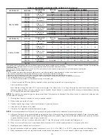
Страница 49: ...66 61 61 61 036080 048080 060080 2 49 44 30 25 25 15 2 1 2 70 70 70 70 70 70 048100 060100 2 1 2 35 26 16 16 6 NA 3 70 70 70 70 66 61 060120 3 14 9 NA NA NA NA 3 no disk 70 70 63 56 50 43 4 no disk 70 70 70 70 70 70 Altitude Unit Size Vent Pipe Diameter In Number of 90 Elbows 1 2 3 4 5 6 3001 to 4000 024040 036040 1 1 2 64 59 54 49 48 43 2 70 70 70 70 70 70 024060 036060 048060 1 1 2 16 11 6 NA NA...

Страница 50: ... 21 16 15 6 2 1 2 70 70 68 67 66 64 048100 060100 2 1 2 27 19 10 9 NA NA 3 68 63 58 53 48 43 060120 3 no disk 31 24 18 11 NA NA 4 no disk 70 70 70 70 67 62 Altitude Unit Size Vent Pipe Diameter In Number of 90 Elbows 1 2 3 4 5 6 7001 to 8000 024040 036040 1 1 2 49 44 39 34 33 28 2 66 65 63 62 60 59 024060 036060 048060 1 1 2 12 7 NA NA NA NA 2 53 48 46 41 40 38 036080 048080 060080 2 36 31 19 14 1...

Страница 51: ...6040 1 1 2 42 37 32 27 25 20 2 57 55 53 51 49 47 024060 036060 048060 2 45 40 38 33 31 29 036080 048080 060080 2 30 25 14 9 7 NA 2 1 2 57 55 53 51 49 47 048100 060100 2 1 2 21 13 5 NA NA NA 3 54 49 44 39 34 29 060120 4 no disk 10 5 NA NA NA NA Wide radius elbow Vent sizing for Canadian installations over 4500 ft 1370 m above sea level are subject to acceptance by the local authorities having juris...

Страница 52: ...less drain trap and drain line have adequate freeze protection See Service and Maintenance Instructions for winterizing procedures See Fig 16 Furnace condensate is mildly acidic typically in the pH range of 3 2 to 4 5 Due to corrosive nature of this condensate a condensate pH neutralizing filter may be desired Check with local authorities to determine if a pH neutralizer is required Fig 56 Direct ...

Страница 53: ...to each side of the centerline extended above or below vent terminal of the furnace to a dryer or water heater vent or other appliance s direct vent intake or exhaust N Clearance to the vent terminal of a dryer vent water heater vent or other appliances direct vent intake or exhaust 1 In accordance with the current CSA B149 1 Natural Gas and Propane Installation Code 2 In accordance with the curre...

Страница 54: ...e trap back See Fig 59 3 Use wire ties to secure heat tape in place Wire ties can be positioned in notches of condensate trap sides See Fig 59 4 Wrap field drain pipe with remaining heat tape approximately 1 wrap per ft 5 When using field supplied heat tape follow heat tape manufacturer s instructions for all other installation guidelines START UP ADJUSTMENTS AND SAFETY CHECK PROCEDURE 1 GENERAL 1...

Страница 55: ...nd replace drain connection cap and clamp PROCEDURE 3 PURGE GAS LINES WARNING FIRE AND EXPLOSION HAZARD Failure to follow this warning could result in a fire explosion personal injury or death Never purge a gas line into a combustion chamber Never test for gas leaks with an open flame Use a commercially available soap solution made specifically for the detection of leaks to check all connections I...

Страница 56: ...G and Y circuits The R to Y circuit starts the outdoor unit and the R to G and Y circuits start the furnace blower motor BLWM on COOL speed The electronic air cleaner terminal EAC 1 is energized with 115 vac when the blower motor BLWM is operating When the thermostat is satisfied the R to G and Y circuits are opened The outdoor unit will stop and the furnace blower motor BLWM will continue operati...

Страница 57: ...splay previous status code 4 times b Inducer motor starts and continues to run until Step f of component test sequence c After 7 seconds the hot surface igniter is energized for 15 sec then off d Blower motor operates on HEAT speed for 10 sec e Blower motor operates on COOL speed for 10 sec f Inducer motor stops 5 Reconnect R lead to furnace control remove tape from blower door switch and re insta...

Страница 58: ...t in reduced furnace life DO NOT bottom out gas valve regulator adjusting screw This can result in unregulated manifold pressure and result in excess overfire and heat exchanger failures NOTE If orifice hole appears damaged or it is suspected to have been redrilled check orifice hole with a numbered drill bit of correct size Never redrill an orifice A burr free and squarely aligned orifice hole is...

Страница 59: ... No Manifold Pressure U S A and Canada U S A 775 43 3 8 42 3 2 42 3 3 42 3 4 42 3 5 Altitudes 800 43 3 5 43 3 7 43 3 8 42 3 2 42 3 3 2001 to 825 44 3 8 43 3 4 43 3 6 43 3 7 43 3 8 3000 850 44 3 6 44 3 7 44 3 8 43 3 5 43 3 6 or 875 44 3 4 44 3 5 44 3 6 44 3 7 43 3 4 Canada 900 44 3 2 44 3 3 44 3 4 44 3 5 44 3 6 Altitudes 925 45 3 7 45 3 8 44 3 2 44 3 3 44 3 4 2001 to 950 45 3 5 45 3 6 45 3 7 45 3 8...

Страница 60: ...ld Pressure U S A Only 700 43 3 6 43 3 7 42 3 2 42 3 3 42 3 4 725 43 3 4 43 3 5 43 3 6 43 3 7 43 3 8 750 44 3 6 44 3 7 43 3 4 43 3 5 43 3 6 775 44 3 4 44 3 5 44 3 6 44 3 7 43 3 4 5001 800 44 3 2 44 3 3 44 3 4 44 3 5 44 3 6 825 45 3 6 45 3 7 44 3 2 44 3 3 44 3 4 to 850 45 3 4 45 3 5 45 3 6 45 3 8 44 3 2 875 45 3 2 45 3 3 45 3 4 45 3 6 45 3 7 6000 900 45 3 0 45 3 1 45 3 3 45 3 4 45 3 5 925 45 2 9 45...

Страница 61: ... No Manifold Pressure Orifice No Manifold Pressure Orifice No Manifold Pressure Orifice No Manifold Pressure U S A Only 600 43 3 8 42 3 3 42 3 4 42 3 5 42 3 6 625 43 3 5 43 3 6 43 3 8 42 3 2 42 3 3 8001 650 44 3 7 43 3 4 43 3 5 43 3 6 43 3 7 675 44 3 5 44 3 6 44 3 7 44 3 8 43 3 4 to 700 44 3 2 44 3 3 44 3 4 44 3 6 44 3 7 725 45 3 6 45 3 8 44 3 2 44 3 3 44 3 4 9000 750 45 3 4 45 3 5 45 3 6 45 3 8 4...

Страница 62: ...nifold Pressure U S A and Canada U S A 775 41 3 7 41 3 8 40 3 6 40 3 7 39 3 6 Altitudes 800 42 3 8 41 3 6 41 3 7 41 3 8 40 3 6 2001 to 825 42 3 6 42 3 7 41 3 5 41 3 6 41 3 7 3000 850 42 3 4 42 3 5 42 3 6 42 3 7 41 3 5 or 875 42 3 2 42 3 3 42 3 4 42 3 5 42 3 6 Canade 900 43 3 7 43 3 8 42 3 2 42 3 3 42 3 4 Altitudes 925 43 3 5 43 3 6 43 3 7 42 3 2 42 3 3 2001 to 950 43 3 3 43 3 4 43 3 5 43 3 7 43 3 ...

Страница 63: ...ssure U S A Only 700 41 3 5 41 3 7 41 3 8 40 3 6 40 3 7 725 42 3 7 42 3 8 41 3 5 41 3 6 41 3 8 750 42 3 4 42 3 5 42 3 7 42 3 8 41 3 5 775 42 3 2 42 3 3 42 3 4 42 3 5 42 3 7 5001 800 43 3 7 43 3 8 42 3 2 42 3 3 42 3 4 825 43 3 5 43 3 6 43 3 7 43 3 8 42 3 2 to 850 43 3 3 43 3 4 43 3 5 43 3 6 43 3 7 875 43 3 1 43 3 2 43 3 3 43 3 4 43 3 5 6000 900 43 2 9 43 3 0 43 3 1 43 3 2 43 3 3 925 43 2 7 43 2 8 4...

Страница 64: ...l to complete 1 revolution g Refer to Table 17 for cu ft of gas per hr h Multiply gas rate cu ft hr X heating value Btu cu ft using natural gas heating value from local gas utility supplier Fig 63 Redundant Automatic Gas Valve A03142 REGULATOR SEAL CAP REGULATOR ADJUSTMENT SCREW REGULATOR SPRING PROPANE WHITE 6 TURNS NATURAL SILVER 10 TURNS GAS PRESSURE REGULATOR ADJUSTMENT MANIFOLD PRESSURE TAP I...

Страница 65: ...temperature rise Table 17 Gas Rate Cu Ft Hr SECONDS FOR 1 REVOLUTION SIZE OF TEST DIAL SECONDS FOR 1 REVOLUTION SIZE OF TEST DIAL 1 cu ft 2 cu ft 5 cu ft 1 cu ft 2 cu ft 5 cu ft 10 11 12 13 14 360 327 300 277 257 720 655 600 555 514 1800 1636 1500 1385 1286 50 51 52 53 54 72 71 69 68 67 144 141 138 136 133 360 355 346 340 333 15 16 17 18 19 240 225 212 200 189 480 450 424 400 379 1200 1125 1059 10...

Страница 66: ...r must be set to match amp draw of the electrical components in R W circuit Accurate amp draw readings can be obtained at thermostat subbase terminals R and W Fig 65 illustrates an easy method of obtaining actual amp draw The amp reading should be taken after blower motor has started and furnace is heating Connect ammeter wires as shown in Fig 65 The thermostat anticipator should NOT be in the cir...

Страница 67: ...cer Check switch operation as follows 1 Turn off 115 v power to furnace 2 Remove main furnace door and disconnect inducer motor lead wires from wire harness 3 Turn on 115 v power to furnace 4 Set thermostat to call for heat and wait 1 minute When pressure switch is functioning properly hot surface igniter should NOT glow and control status code LED light flashes a Status Code 31 If hot surface ign...

Страница 68: ..._____ Pipe Sloped To Furnace Pipe Insulation ________ Over Ceilings ________ Low Ambient Exposed Pipes Condensate Drain ________ Unit Level or Pitched Forward ________ Internal Tubing Connections Free of Kinks and Traps ________ External Drain Connection Leak Tight and Sloped ________ Condensate Trap Primed before Start Up ________ Heat Tape Installed if Required CHECKLIST START UP ________ Gas In...

Страница 69: ...______ Low Ambient Exposed Pipes Condensate Drain ________ Unit Level or Pitched Forward ________ Internal Tubing Connections Free of Kinks and Traps ________ External Drain Connection Leak Tight and Sloped ________ Condensate Trap Primed before Start Up ________ Heat Tape Installed if Required CHECKLIST START UP ________ Gas Input Rate Set Within 2 percent of Rating Plate ________ Temperature Ris...

Страница 70: ... 70 ...

Страница 71: ... 71 ...

Страница 72: ... 2005 Payne Heating Cooling 7310 W Morris St Indianapolis IN 46231 72 impg9m10 Catalog No 53PG 9M29 ...

Отзывы: