9
Joint operation with heat-producing appliances
In case of simultaneous operation with heat-producing appliances, e.g. chimneys, the corresponding standards and
regulations must be complied with by the qualified personnel. The joint operation of indoor air-dependant heat-
producing appliances and ventilation plants requires an appropriate safety device (differential pressure switch) or a
plant-specific measure, in the event that dangerous negative pressures can be generated in the installation room of
the heat-producing appliance during operation.
Available control modules
The CLIMOS can be equipped with the following control panels:
•
External control panel (W x H x D in mm: 71 x 71 x 25)
•
External control signal (0-10 V)
•
External boost ventilation switch (any number, potential-free)
External control panel
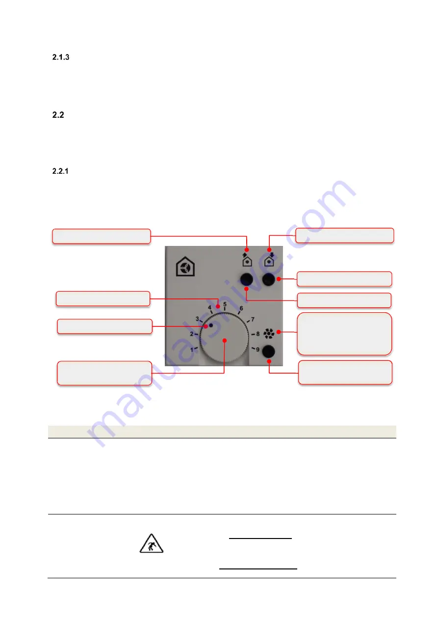
The operating panel is equipped with a rotary knob for stepless control of the ventilators with a 9-step scaling for the
air volume flow. The two ON/OFF buttons are used to select the operating mode. Either normal mode (both
ventilators on), or extract air (only exhaust air ventilator on) or supply air mode (only supply air fan on) can be
selected. The selected operating mode is indicated by green a LED of the respective symbol. The operating functions
are carried out with the button boost ventilation mode / reset filter runtime. The fan-symbol with the red LED signals
the respective operating mode depending on the function.
2.2.1.1
Operating functions control panel
Description
Explanation
Positioning rotary knob
Un-occupied mode:
intermittent operating mode with the smallest air volume flow
Pos. min (rotary knob on the left): 5 min ON and 1 min OFF
Position 1: 3 min ON and 3 min OFF
Pos. below 2: 1 min ON and 5 min OFF
Position rotary knob between Pos. min and below 2: cycling proportional
Operating-mode:
Position 2: smallest air volume flow
Position 9: largest air volume flow
Position rotary knob between Pos. 2 and Pos. 9: air volume flow proportional
Push button extract air
mode
The extract air mode and the exhaust air fan are set by pushing and locking. By
pushing again the extract air mode is deactivated again.
This push button cannot be operated when the ventilation device is
run with a heat-producing appliance, unless the supply air mode is
activated simultaneously! The simultaneous operation of the
ventilation device and the heat-producing appliance has increased safety-
related requirements for low pressure monitoring with a switch-off function for
the ventilation device.
Rotary knob for setting of air
volume flow
Present position rotary knob
Extract air symbol with green LED
Supply-air symbol with green LED
ON/OFF-button supply mode
ON/OFF-button exhaust mode
Button boost ventilation mode /
Reset filter runtime
Fan-symbol with red LED for
un-occupied mode /
boost ventilation mode /
filter control
Scale 1 - 9
Fig 2: Control and information panels control panel
Содержание CLIMOS F 200 Eco
Страница 1: ...Version 1 1_08 2019 EN...
Страница 32: ...32 Dimensional sketch Fig 44 Dimension drawing...
Страница 33: ...33 Circiut diagram CLIMOS Eco series Fig 45 Terminal assignment CLIMOS Eco...
Страница 38: ...38 Product fiche...


