background image

11


*To Re-Assemble the Machine reverse the above procedure.  Hopper bolts should only be hand 
tightened with the speed driver provided. 

*The Knock Out Cup Should be installed on the Machine before the Feed Tray and Mold Plate 
Guard, but after all other parts are in place.  The Mold Plate should be all the way forward and the 
Knock Out Arm should be in the down position for the cup to align with the Mold Plate properly.

Patty-O-Matic Inc. offers the highest quality patty paper, machine lubricant, and 

machine grease.  Please contact the factory for information on these products. 

732-938-5244              www.pattyomatic.com                [email protected]


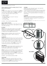
Paper Sleeves Stops should be 

adjusted for different size patty paper

- Remove the Knock Out Cup by loosening 
the Knock Out Knob while holding the other 
end of the bolt with the Speed Driver 
provided with the machine.

- All of the parts that were removed from the 

machine can now be washed and sanitized 
thoroughly.  USDA recommends the 
sanitizing solution should be 50 parts per 
million but no more than 200 parts per 
million.  The machine itself should be 
cleaned and sanitized by hand.  After all 
the parts are cleaned, sanitized and dry 
they should be coated in mineral oil as an 
extra protectant. 

DO NOT HOSE DOWN OR PRESSURE 

WASH THIS MACHINE! 

Installing Patty Paper on Interleaver 


-Place a stack of paper no thicker 
than 1 inch under the pressure foot.  
Slide the hole in the paper over the 
center pin.  

*Placing more than 1 inch of paper 
may cause improper paper feeding.

Center Pin

Shown without guard for better visual

Knock Out Knob

Speed Driver

Pressure Foot

Paper Sleeve Stops

Knock Out Cup

Содержание PS21

Страница 1: ...1 Owner s Manual Revised October 2019 Patty O Matic Inc Route 547 P O Box 404 Farmingdale NJ 07727 732 938 2757 Toll Free in USA 877 938 5244 www pattyomatic com info pattyomatic com E469483 NSF ANSI...

Страница 2: ...ssembly Page 13 Mold Plate Guard Assembly Page 13 Knock Out Cup Assembly Page 13 Hopper Assembly Page 14 Feeder Assembly Page 14 Assembled Machine Views Page 15 Paper Interleaver Assembly Page 16 Ring...

Страница 3: ...paper between and stack patties This machine is designed for easy operation and cleaning Please become familiar with this manual and your machine will give you many years of service The Model PS21 is...

Страница 4: ...Holds Spare Parts Patty Paper Sample Machine Lubricant Speed Driver and Locator Rings c w instructions 2 Receiving Table 609 6 3 Speed Driver 544 4 8 Ounce Bottle of Machine Lubricant and Cleaner 600...

Страница 5: ...ate Guard are installed for your safety Do not tamper with them in any way Mold Plate Guard Knock Out Cup Assembly Refer to Page 12 Please become familiar with some of the parts of your machine prior...

Страница 6: ...6 Proper Label Location for a Model PS21 9 2 3 1 5 6 7 2 10 5 11 9 12 4 8...

Страница 7: ...514 02 3 Patty O Matic 514 08 4 Safety instructions 514 06 5 Danger Label 2 514 00 6 Serial Tag For UL Machines 514 15UL 7 Store Tool 514 14 8 Warning Manual 514 01 9 Danger on off 514 05 10 Do Not Pr...

Страница 8: ...le 3 3 ounce hole 4 4 ounce hole 5 5ounce hole 6 6 ounce hole 7 7 ounce hole 1 8 4 7 Proper Procedure for Operating a PS21 When the Model PS21 is fully assembled with all guards secured in their prope...

Страница 9: ...late and Knock Out Cup The thickness fraction stamped on the Double Seal Spacer Plate should match the fraction stamped on the front right corner of the Mold Plate For example if your Mold Plate is st...

Страница 10: ...wed from the Back Drive as an alternate means of disassembly Proper Disassembly for Cleaning your Model PS21 Always Unplug Machine from its Electrical Source Before Cleaning Loosen the two Hopper Bolt...

Страница 11: ...Knock Out Cup by loosening the Knock Out Knob while holding the other end of the bolt with the Speed Driver provided with the machine All of the parts that were removed from the machine can now be wa...

Страница 12: ...drops of oil There are two Rod End Bearings to be oiled Do not allow oil to drip onto the Conveyor Belt Main Shaft should be oiled when the machine is disassembled as shown in this picture Be sure to...

Страница 13: ...lastic Washer 571 6 10 Round Knock Out Cup Specify Size 571 1 11 Knock Out Cup Flat Washer and Lock Washer 571 8 12 Knock Out Air Valve shown in red for visual affect 571 4 13 Knock Out Cup Bolt 571 9...

Страница 14: ...ck Hardware 548 CR 8 Pressure Plate Block Assembly PS21 547 YR 9 Feeder PS21 557 10 Retaining Rod Spring 551 1A 11 Hopper Threaded Plug 607 12 Guard Block Mounting Screws PS21 551 C1 13 Feeder Washer...

Страница 15: ...ing 701 32 Knock Out Spring Threaded Holder 490E 33 Ring Pin 546C 34 Weight Shaft Support Hardware 530 Item Description Part 1 Paper Interleaver Arm and Bolts PS21 505 2 Knock Out Arm and Bolts 502B 3...

Страница 16: ...5 Stainless Steel Paper Pivot Rod 2 247 16 Paper Stop 248 17 2 Return Bracket Mounting Screws249 18 Left Return Spring 246L 19 Right Return Spring 246R Item Description Part 20 Spring Adjusting Collar...
Страница 17: ...7 Air Grooves colored for visual N A 8 Round Mold Plate Only 563 1 9 Set of Back Drive Hardware 568A Item Description Part 10 Back Drive Clamp 568 11 T Knob 567 12 Hopper Casting PS21 545 13 Hold Down...

Страница 18: ...Guard 501 3 On Off Switch Boot 500B 4 Power Cord 115 01 5 Wire Grommet 487 6 Guard Switch 608 1B 7 Guard Switch Wire 608 1D 8 On Off Switch insulated in electrical tape 500 9 Tower Switch 620 10B 10 T...

Страница 19: ...m 620 3 3 Tower Tube 620 5 4 Tower Block 620 6 5 Tower Locator Lock Bolt 620 7 6 Tower Switch 620 10B 7 Rubber Seal 464S 8 Tower Block Hardware 620 8 9 Tower Jam Nut 620 06 10 Tower Spring 620 9 11 To...

Страница 20: ...ressed into Machine Frame 464A 6 Timing Chain and Link 471 7 Main Shaft Clamp 467 8 Main Shaft Clamp Hardware 468 9 Main Shaft Fender Washer and Hardware 240 1 10 Main Shaft Driven Sprocket Specify Am...

Страница 21: ...ocket 460 9 Timing Chain and Link 471 10 Crank Arm Hardware 453 11 Connecting Arm Thrust Washer 456B 12 Connecting Arm Cotter Pin 455A 13 Connecting Arm Bushing white poly bushing pressed into the Con...

Страница 22: ...29B 5 Idler Arm Shoulder Bolt 229A 6 Idler Arm 230 A 7 Idler Arm Sprocket and Bushing Assembly 232 8 Idler Arm Spring Tab 231A 9 Idler Arm Spring Tab Hardware 231B 10 Main Shaft Fender Washer and Hard...

Страница 23: ...nock Out Lever Hardware 451 9 Knock Out Lever Bushing Hardware 450B 10 Cam Follower Bearing 474 11 Steel Knock Out Cam Bolts 2 472 S1 12 Steel KO Cam Keeper Bolt and Hardware 472 S2 13 Knock Out Lever...

Страница 24: ...Set Screw 464 1 10 Mold Plate Guide Rail Bolts set of 2 bolts 495 11 Hold Down Bolt 556B 12 Mold Plate Guard Rear Post Assembly PS21 551 D 13 PS21 Guide Rail PS21 494 14 PS21 Guide Rail Button Bolts...

Страница 25: ...AL B BLACK 115 VAC G GREEN GROUND 115 VAC 15A CIRCUIT BREAKER GROUND LIMIT SWITCH PAPER INTERLEAVER MOTOR MAIN MOTOR COM POWER OFF 115 V 1 PHASE 60 CYCLE 13 AMPS 1 2 HP POWER ON NO NC NOT USED LIMIT S...

Страница 26: ...e has been plugged into any current other than that specified or has been tampered with or altered in any way Warranty does not cover parts that wear out from use or parts that are damaged or broken i...

Страница 27: ...formed on Machine______________________________ ___________________________________________________ ___________________________________________________ ________________________________________________...

Страница 28: ..._____________________ ______________________________________________________ ______________________________________________________ ______________________________________________________ _____________...

Отзывы: