


– 9 –
4
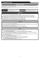
Installation
Caution
This product is for indoor use only. (Do not use it outdoors.)
Do not leave the product, or use it without globe installed.
Do not apply excessive force when mounting/removing the globe. Failure to comply will result in damage.
When removing and installing the globe again, check that there is no gap between the globe and case.
A gap may result in parts falling in or water ingress.
Use a soft cloth moistened with water to clean the globe or case.
(Do not use thinner, benzine, gasoline or oil.)
The waterproof sheet must be used before installation.
This product has a 1mm thick waterproof sheet at the bottom of the case. However, because installation surface
unevenness may cause a lack of waterproo
fi
ng protection, it is recommended to apply sealant between the unit and the
installation surface to maintain waterproof conditions.
Notice
The following requirements are necessary for proper installation:
- Install the signal beacon where excessive
vibration
is not present.
- lnstall the signal beacon on a
sturdy
surface.
- Install the signal beacon on a
level
surface.
When waterproo
fi
ng, apply a sealing coating onto the nuts on the backside of the installation surface.
Provide a sealant coating around the wire exit hole, or use a Cable Gland.
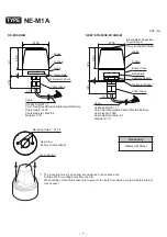
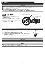
TYPE
NE-24A
(1) (5)
(2)
(3)
(4)
Installation Example
Positioning Mark
< Locked >
< Unlocked >
(1) Unlock the globe by holding and rotating it in a counter-
clockwise direction, then lift it up.
(2) Punch-out the mounting holes on the case by drilling
Ø 4.5 holes from the top.
(3) Peel off the adhesive paper from the waterproof sheet
and apply it to the case.
(4) Af
fi
x the product to the installation surface with screws
and nuts.
(Installation screws and nuts are not included with this
product.)
(5) After mounting the case,
fi
t the globe by aligning the
positioning marks and lock it by rotating in a clockwise.
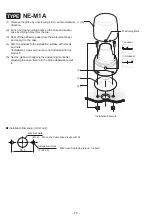
Installation Dimension [Unit: mm]
35.5
Wire Exit Hole
Installation Holes
(Ø 16)
(2 - Ø 4.5)
M4 screw
(Tightening torque: 0.6 N•m)
When the Cable Gland is used: Ø
26
When the Cable Gland is used, the hole must be large enough for it to
fi
t through.
The recommended Cable Gland size is as follows:
screw size: M16 × 1.5; screw length: shorter than 11 mm;
outer diameter: less than 25 mm;
material: plastic. (Tightening torque : 3 N•m)


