APPENDIX B
119
Appendix B – Encoder & Resolver Phasing
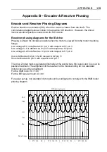
Encoder and Resolver Phasing Diagrams
Positive direction is clockwise (CW) when the motor is viewed from the shaft. The
commutation diagrams show motion in the positive CW direction. However, the drive’s
internal electrical position counts down for CW motion.
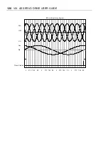
Resolver phasing diagrams for the IE drive
Phasing is shown for clockwise rotation when the motor is viewed from the motor mounting
flange.
Line voltage W-V is defined as X1 pin 2 with respect to X1 pin 3
Line voltage V-U is defined as X1 pin 3 with respect to X1 pin 4
Line voltage U-W is defined as X1 pin 4 with respect to X1 pin 2
Cos is defined as X2 pin 12 with respect to X2 pin 11
Sin is defined as X2 pin 8 with respect to X2 pin 7
The drive Z index mark is generated internally at the point where Sin is zero and Cos is at its
positive maximum. The alignment of the resolver to the motor winding for non standard
motors can be set by adjusting IX
For the SMB motor IX = 180
For the BE resolver motor IX = 90
For easier set up, non standard motors should be configured to comply with the SMB motor
phasing diagram.
90
180
270
0
90
180
270
0
90
180
270
0
90
180
270
0
Drive Z index
Sin
Cos
V-U
U-W
W-V
SMB phasing diagram
Содержание ViX250AE
Страница 2: ......
Страница 57: ...50 VIX AE SERVO DRIVE USER GUIDE...
Страница 123: ...116 VIX AE SERVO DRIVE USER GUIDE...
Страница 135: ......

